Eureka AIR delivers breakthrough ideas for toughest innovation challenges, trusted by R&D personnel around the world.

Methods of producing useful energy from thermal energy

A technology of useful energy and thermal energy, applied in the direction of electric motors that apply thermal effects, thermoelectric devices that only use Peltier or Seebeck effects, steam engine devices, etc.

Active Publication Date: 2016-12-14
约阿夫·科恩
View PDF8 Cites 0 Cited by
  • Summary
  • Abstract
  • Description
  • Claims
  • Application Information

AI Technical Summary

Problems solved by technology

[0002] The inventor of this patent application discloses a method and a device in the patent application WO 2010 / 115654. The method and device are based on the principle of action related to the present invention, but they are limited to applications in centrifugal force fields. Centrifugal force field acts on a fluid that requires the state to be an ideal gas or an ideal liquid

Method used


Image

  • Methods of producing useful energy from thermal energy
  • Methods of producing useful energy from thermal energy
  • Methods of producing useful energy from thermal energy

Examples


Embodiment Construction

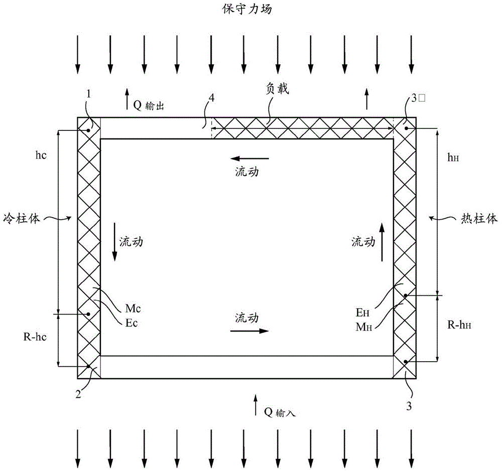
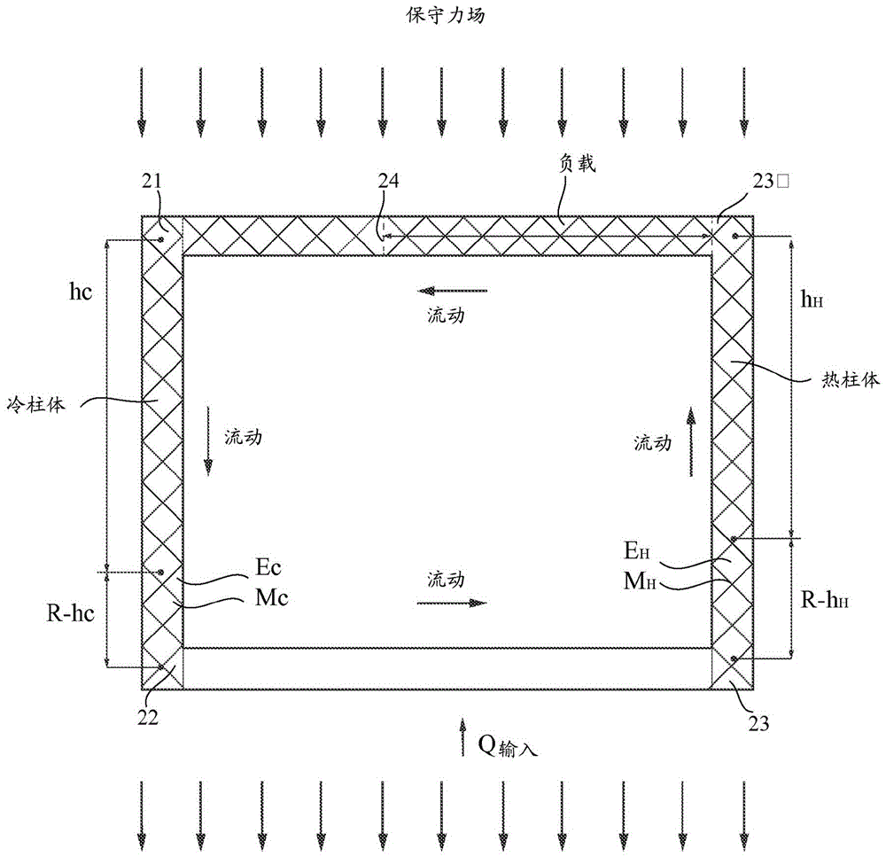
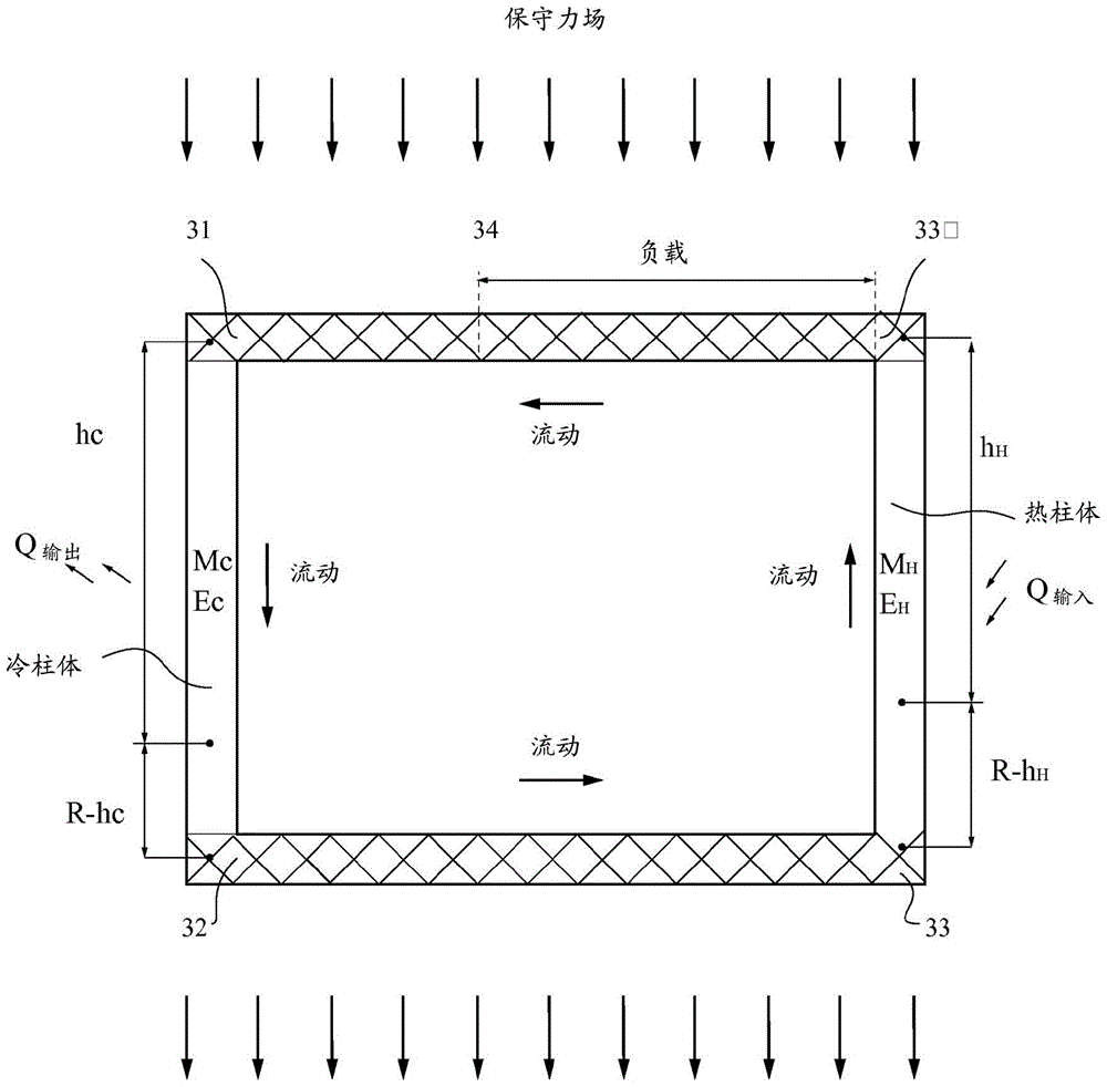
[0029] Choice of method: The method is manifested in several ways. In order to provide a sufficiently broad application of the method, the method is analyzed here by means of two preferred representative construction examples: one example is that by means of which heating is carried out in the circuit line 2-3, in the circuit line 4-1 Refrigerated, and insulated in the remainder of the process ( figure 1 ). Another example is by which heat is supplied in circuit ducts 33-33', cooling is provided in circuit ducts 31-32, and the rest of the process is insulated ( image 3 ). The load is indicated as being on the return pipe 3'-4 or 33'-34. In an actual method, the heating structure can be changed, and can also be based on a combination of these two preferred solutions.

[0030] The first option above: according to figure 1 , the general basic form of the method consists of moving particles, being charged particles, confined in a closed loop 1-2-3-3'-4-1 inside a conductiv...


PUM


Abstract

The present invention relates to a method of generating useful energy from thermal energy. The total population of moving particles is confined in the closed loop of the conduction pipe and flows unidirectionally under the action of a conservative force field. The circuit is insulated except for two non-parallel areas, the first allowing heat exchange with the warmer environment outside the circuit for heating and the second allowing heat exchange with the cooler environment outside the circuit for cooling. A load is placed on the closed loop for the purpose of converting the energy received by the load from the flow of moving particles into useful output energy. Two parts of a one-way loop before and after the load, the velocity vector or components of the vector are parallel to the conservative force field; one of the two parts has a hot flow of moving particles and the other has a cold flow of moving particles, when the selected movement When the density of particles decreases with increasing temperature, the direction of the conservative force field is the same as or with the same component as the velocity vector of the cold flow in the loop section, and when the density of moving particles increases with increasing temperature, In the opposite direction.

Description

technical field [0001] The present invention relates to a method for generating useful energy from thermal energy. Background technique [0002] The inventor of this patent application discloses a method and a device in the patent application WO 2010 / 115654. The method and device are based on the principle of action related to the present invention, but they are limited to applications in centrifugal force fields. Centrifugal force fields act on fluids that require the state to be either an ideal gas or an ideal liquid. [0003] German patent application DE 102 34 568 A1 and international patent application WO 2010 / 097260 disclose methods based on the principle of action relevant to the present invention, but which are limited to methods applied in gravitational fields, which A gravitational field acts on a fluid that requires the state to be either an ideal gas or an ideal liquid. [0004] US patent application US 7,486,000 B1 discloses a method using known heat sources, ...

Claims


Application Information

Patent Timeline
Patent Type & Authority Patents(China)
IPC IPC(8): F01K13/00F01K25/00H01L35/28H10N10/00H10N10/10
CPCF01K25/00F01K13/00F01K27/00H02N10/00
Inventor 约阿夫·科恩
Owner 约阿夫·科恩
Why Eureka
Eureka Blog
Learn More