Contact point mechanism part, and electromagnetic relay provided with same

A contact mechanism and moving contact technology, applied in electromagnetic relays, electromagnetic relay details, relays, etc., can solve problems such as high power consumption and large driving force, and achieve less power consumption, improved reliability, and high-precision control. Effect

Active Publication Date: 2015-04-08
ORMON CORP
View PDF5 Cites 8 Cited by
  • Summary
  • Abstract
  • Description
  • Claims
  • Application Information

AI Technical Summary

Problems solved by technology

As a result, a large driving force is required for the armature 10 for separation, and there is a problem of high power consumption.

Method used


Image

  • Contact point mechanism part, and electromagnetic relay provided with same
  • Contact point mechanism part, and electromagnetic relay provided with same
  • Contact point mechanism part, and electromagnetic relay provided with same

Examples


Embodiment Construction

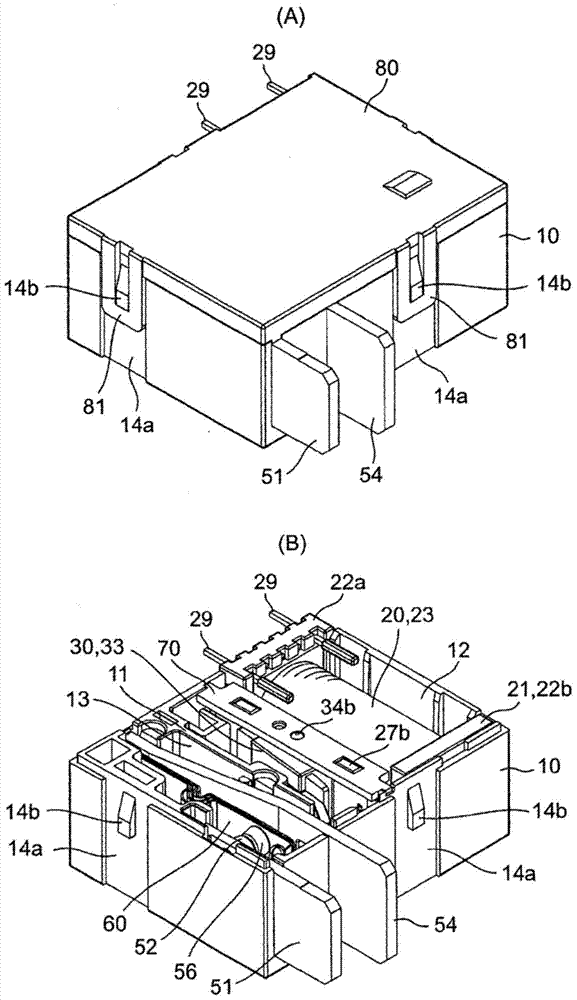
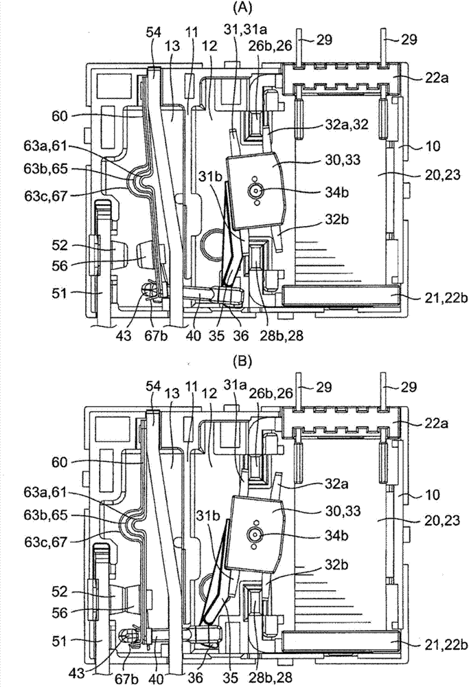
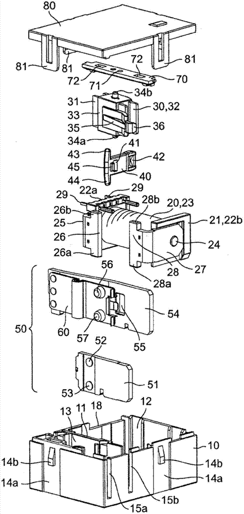
[0082] refer to Figure 1 to Figure 10 An electromagnetic relay as an embodiment to which the present invention is applied will be described.

[0083] The electromagnetic relay of the first embodiment is composed of a box-shaped base 10 , an electromagnet block 20 , a rotating block 30 , a card 40 , a contact mechanism portion 50 , a support plate 70 , and a cover 80 .

[0084] Such as Figure 5 As shown, the box-shaped base 10 is a flat square shallow-bottomed box, and its interior is separated by an insulating wall 11 having an operation cutout 11a, and a first concave portion 12 and a second concave portion 13 are formed therein. In addition, the box-shaped base 10 has a shallow groove 14a extending up and down along its outer surface, and a locking receiving portion 14b protrudes from the bottom surface of the shallow groove 14a.

[0085] The first concave portion 12 is provided with a bearing portion 16 on the bottom surface thereof for supporting a rotating shaft porti...


PUM


Abstract

In this contact mechanism part, driving protrusion parts (43, 44) disposed on one end of a card (40) that slides engage with the free edge part of a moveable contact piece (60), the moveable contact piece (60) is turned by sliding the card (40), and moveable contact points (56, 57) provided to the moveable contact piece (60) come into and out of contact with fixed contact points (52, 53). In particular, the present invention is provided with a pair of driving protrusion parts (43, 44) which protrudes in the opposite direction from corner parts adjacent to the one end of the card (40), and a pair of elastic returning tongue pieces (67b, 67c) which is cut out of the free edge part of the moveable contact piece (60) and which is arranged so as to be able to come into contact with the driving protrusion parts (43, 44). When the moveable contact points (56, 57) and the fixed contact points (52, 53) come into contact with one another, the distance between one of the driving protrusion parts (43) and one of the elastic returning tongue pieces (67b) becomes shorter than the distance between the other driving protrusion part (44) and the other elastic returning tongue piece (67c).

Description

technical field [0001] The present invention relates to a contact mechanism unit, and particularly to a contact mechanism unit incorporated in a switch device such as an electromagnetic relay. Background technique [0002] Conventionally, as a contact mechanism unit incorporated into a switch device such as an electromagnetic relay, as in Patent Document 1, figure 1 As shown, the armature 10 is rotated based on the application and stop of the voltage to the electromagnetic coil 8, whereby the actuator 13 is slid up and down. Therefore, the actuator 13 rotates the elastic contact piece 4 and makes the contact button 6 contact and separate from the second relay contact 3 . [0003] Patent Document 1: Specification of (US) Patent No. 6,661,319 [0004] However, in the above-mentioned contact mechanism part, since the protruding part 15 provided at the lower end part of the actuator 13 is substantially U-shaped, the separation force at the time of reset is applied substantiall...

Claims


Application Information

Patent Timeline
Patent Type & Authority Applications(China)
IPC IPC(8): H01H50/64H01H50/56
CPCH01H50/56H01H50/64H01H1/28H01H3/001H01H50/24H01H50/58H01H50/642H01H51/2227H01H51/24H01H50/645
Inventor 小材裕二田中弘泰古庄伸一
Owner ORMON CORP
Why Eureka
Try Eureka