
Hot rolled strip steel convexity control method

A hot-rolled strip steel and control method technology, applied in the direction of contour control, etc., can solve the problems that the crown accuracy of the strip steel cannot be guaranteed and the stability of the full-length crown, and achieve the effect of ensuring the crown accuracy and

Active Publication Date: 2015-04-15
BAOSHAN IRON & STEEL CO LTD +1
View PDF9 Cites 36 Cited by
  • Summary
  • Abstract
  • Description
  • Claims
  • Application Information

AI Technical Summary

Problems solved by technology

[0010] Aiming at the problem that in the production and rolling process of hot-rolled strip steel, when there is a deviation in crown setting or a large change in rolling conditions, the crown accuracy and full-length crown stability of the strip cannot be guaranteed. The purpose of this paper is to propose a method for controlling the crown of hot-rolled strip steel, so as to improve the precision of crown control of strip steel products and improve the quality of product crown

Method used


Image

  • Hot rolled strip steel convexity control method
  • Hot rolled strip steel convexity control method
  • Hot rolled strip steel convexity control method

Examples


Embodiment 1

[0052] For a hot rolling mill, roll a carbon steel product with a specification of 3*1250mm. The thickness of the incoming material is 37mm, and the target convexity is 30μm (tolerance range ±20μm). The main roll system parameters of the rolling mill are shown in Table 1, and the rolling conditions are shown in Table 2.

[0053] Table 1 Rolling Mill Roll System Parameters (unit: mm)

[0054]

[0055] Table 2 rolling conditions

[0056]

[0057] The plate shape setting parameters calculated by the mathematical model are shown in Table 3 below.

[0058] Table 3 Shape setting data

[0059]

[0060] Automatic crown control is implemented after strip threading, and crown self-learning is performed after rolling. Figure 4 Shown is the bending force of the F2 frame with the adjustment curve of the strip crown.

Embodiment 2

[0062] For a hot rolling mill, roll a carbon steel product with a specification of 3*1250mm. The thickness of the incoming material is 37mm, and the target convexity is 30μm (tolerance range ±20μm). The main roll system parameters of the rolling mill are shown in Table 1. The rolling conditions are shown in Table 4.

[0063] Table 4 rolling conditions

[0064]

F1

F2

F3

F4

F5

F5

F7

Thickness / mm

21.83

14.24

9.632

6.782

5.159

7.86

3.606

Speed / m / s

1.46

2.27

3.36

4.78

6.29

8.14

9.0

[0065] temperature / ℃

1029.4

1025.8

1021.8

1016.7

1011.2

1004.8

997.6

[0066] The plate shape setting parameters calculated by the mathematical model are shown in Table 5 below. Automatic crown control is implemented after strip threading, and crown self-learning is performed after rolling. Figure 5 Shown is the bending force of the F2 fra...


PUM


Abstract

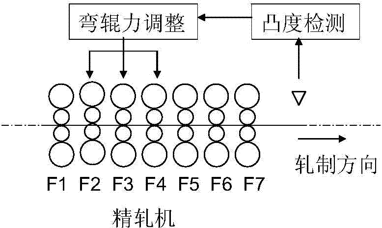
A hot rolled strip steel convexity control method comprises the steps of according to original roll profiles, abrasion, thermal expansion of rollers and concrete rolling conditions (such as rolling force, plate width and plate thickness), utilizing a mathematic model to calculate plate shape setting and controlling parameters such as roll bending force and crossing angles of the rollers; after threading of a strip steel, carrying out automatic convexity control, which comprises roll bending force compensation for roller thermal convexity change, roll bending force compensation for rolling force change and actual measurement convexity feedback control; according to actual measurement strip steel convexity and target convexity, utilizing the mathematic model to carry out convexity self-learning so as to improve the setting precision of the next roll of strip steel. According to the hot rolled strip steel convexity control method, the strip steel convexity precision and the overall length convexity stability can be effectively guaranteed under the condition that deviation appears in the convexity setting or the rolling conditions drastically change.

Description

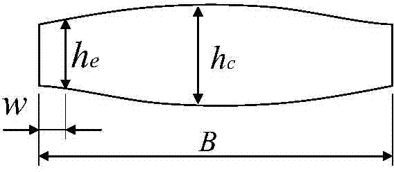
technical field [0001] The invention relates to the field of hot-rolled steel strip production, in particular to a method for controlling the crown of a hot-rolled strip steel, which is suitable for the shape quality control of hot-rolled strip steel products. Background technique [0002] Crown is an important quality index of hot-rolled strip products. There are different requirements for the convexity of finished products for different purposes. The finished hot-rolled steel strip for direct use is expected to have a cross-sectional shape close to a rectangle, that is, the convexity is as small as possible; while the hot-rolled strip steel used as a cold-rolled raw material requires a certain convexity. [0003] Such as figure 1 As shown, the so-called convexity refers to the difference between the thickness of the center of the strip steel and the thickness of the representative point of the edge: [0004] C h =h c -h e [0005] Among them, B is the strip width, C...

Claims


Application Information

Patent Timeline
Patent Type & Authority Applications(China)
IPC IPC(8): B21B37/28
CPCB21B37/28
Inventor 张国民焦四海杨宴宾詹世明
Owner BAOSHAN IRON & STEEL CO LTD
Learn More