Lamp cap swing mechanism

A technology of swing mechanism and lamp cap, which is applied to lighting devices, lighting device parts, lighting auxiliary devices, etc., can solve the problems of unstable work, complex realization mechanism, complicated mechanism, etc., and achieve the effect of rapid swing and simple structure.

Active Publication Date: 2015-04-15
SHENZHEN OCEANS KING LIGHTING ENG CO LTD +1
View PDF3 Cites 6 Cited by
  • Summary
  • Abstract
  • Description
  • Claims
  • Application Information

AI Technical Summary

Problems solved by technology

Compared with the former, the latter has a more complicated mechanism for realizing the swing of the lamp head.
In the prior art, the implementation mechanism of the latter is complicated, the operation is unstable, the noise is large, and the swing speed of the lamp head is slow.

Method used


Image

  • Lamp cap swing mechanism
  • Lamp cap swing mechanism

Examples


Embodiment Construction

[0022] In order to make the object, technical solution and advantages of the present invention clearer, the present invention will be further described in detail below in conjunction with the accompanying drawings and embodiments. It should be understood that the specific embodiments described here are only used to explain the present invention, not to limit the present invention.

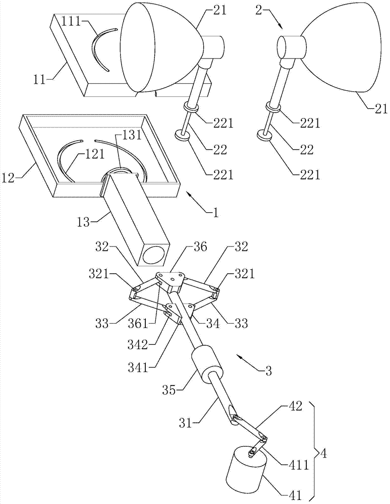
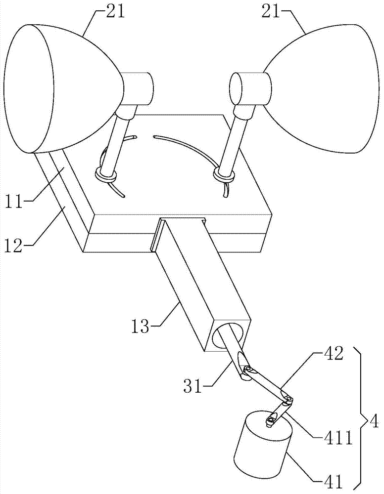
[0023] see figure 1 and figure 2 , the embodiment of the present invention provides a lamp head swing mechanism, including:

[0024] The shell assembly 1 includes an upper shell 11, a lower shell 12 and a guide cylinder 13, the upper shell 11 is covered on the lower shell 12 to form a shell, the shell has a cavity, and the guide cylinder 13 Located on the housing, the upper shell 11 is provided with at least one first arc-shaped long hole 111 , and the lower shell 12 is provided with a second arc-shaped long hole corresponding to the first arc-shaped long hole 111 121;

[0025] The lamp cap as...


PUM


Abstract

The invention provides a lamp cap swing mechanism. The lamp cap swing mechanism comprises a shell component, a lamp cap component, a linkage component and a power component, wherein the shell component comprises an upper shell, a lower shell and a guide cylinder; the upper shell covers the lower shell to form one shell; the shell is provided with a cavity; the guide cylinder is arranged on the shell; the upper shell is provided with at least one first arc-shaped slotted hole; the lower shell is provided with a second arc-shaped slotted hole corresponding to the first arc-shaped slotted hole; the lamp cap component comprises a lamp cap and a rotating shaft; the rotating shaft is arranged at the lower end of the lamp cap and is inserted into the first arc-shaped slotted hole and the second arc-shaped slotted hole; the linkage component is used for driving the rotating shaft to slide in the first arc-shaped slotted hole and the second arc-shaped slotted hole and comprises a movable rod and a first hinge rod; the movable rod is inserted into the guide cylinder and penetrates into the cavity; one end of the first hinge rod is hinged to the movable rod, and the other end of the first hinge rod is provided with a shaft hole for the rotating shaft to pass through; the power component is used for driving the movable rod to do reciprocating motion in the guide cylinder; the movable rod is connected with the power component. According to the mechanism, the lamp cap can stably and quickly swing within a certain angle to emit light in a sweeping manner.

Description

technical field [0001] The invention belongs to the technical field of lamps, and in particular relates to a lamp head swing mechanism. Background technique [0002] In the application of lamps and lanterns, it is often necessary to swing the lamp head to produce special light sweeping effects. The lamps with swingable lamp head are mainly divided into two types: 1) the lamp head can complete 360° swing; 2) the lamp head can complete a certain angle swing. Compared with the former, the latter has a more complicated mechanism for realizing the swing of the lamp head. In the prior art, the implementation mechanism of the latter is complicated, the work is unstable, the noise is large, and the swing speed of the lamp head is slow. Contents of the invention [0003] The object of the present invention is to overcome the defects of the prior art, and provide a lamp cap swing mechanism that can swing the lamp cap rapidly and stably. [0004] The present invention is achieved ...

Claims


Application Information

Patent Timeline
IPC IPC(8): F21V21/14
CPCF21V21/14
Inventor 周明杰张军强
Owner SHENZHEN OCEANS KING LIGHTING ENG CO LTD
Why Eureka
Try Eureka