Terahertz pulse detector based on electro-optic sampling principle

A technology of terahertz pulse and electro-optical sampling, which is applied in the field of signal detection, can solve the problem of low signal-to-noise ratio of terahertz signals, and achieve the effect of improving signal-to-noise ratio and dynamic range

Active Publication Date: 2015-04-15
BEIJING INST OF ENVIRONMENTAL FEATURES
View PDF2 Cites 3 Cited by
  • Summary
  • Abstract
  • Description
  • Claims
  • Application Information

AI Technical Summary

Benefits of technology

The technical effect of this patented technology is that it improves how well signals can be detected from very small amounts (a few nanoseconds) down to extremely low levels (0-100 ppm). This improvement allows for better detection capabilities at different frequencies or wavelength ranges through use of specific components such as silicon germanium bipolar transistors and matched resistances.

Problems solved by technology

This patented technical problem addressed by this patents relates to developing highly sensitive and efficient detecting techniques that use quantum effects (QE) or other technologies such as optics to improve the performance of semitransport devices like THz radars.

Method used


Image

  • Terahertz pulse detector based on electro-optic sampling principle
  • Terahertz pulse detector based on electro-optic sampling principle
  • Terahertz pulse detector based on electro-optic sampling principle

Examples


Embodiment Construction

[0022] In order to make the technical problems, technical solutions and advantages to be solved by the present invention clearer, the following will describe in detail with reference to the drawings and specific embodiments.

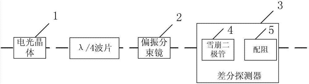
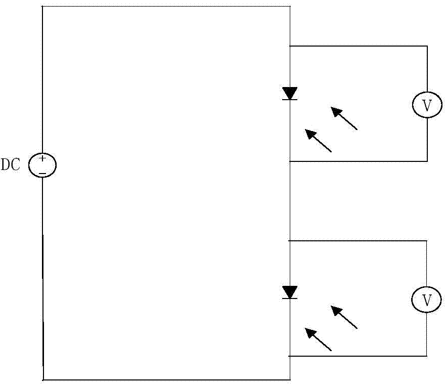
[0023] The electro-optic sampling method is used to detect the terahertz pulse. The laser beam and the terahertz pulse are collinearly passed through the electro-optic crystal with a crystal plane orientation of . The terahertz pulse is irradiated on the electro-optic crystal, and the refractive index ellipsoid of the electro-optic crystal will be Its change, this change will cause the polarization state of the detection laser to change from linear polarization to elliptical polarization, and then divide it into two beams of s polarization and p polarization through a polarization beam splitter (commonly used as a Wollaston prism), and The light intensity difference between the two beams is proportional to the terahertz electric field. Using a differenti...


PUM


Abstract

The invention provides a terahertz pulse detector based on an electro-optic sampling principle. The terahertz pulse detector comprises an electro-optic crystal, a lambda/4 wave plate, a polarization beam splitter and a differential detector, and the differential detector comprises an avalanche diode and a matching resistor which are connected. The avalanche diode and the matching resistor are arranged in the differential detector and connected, so that signal-to-noise ratio and dynamic range of terahertz signals are increased greatly.

Description


Claims


Application Information

Patent Timeline
Owner BEIJING INST OF ENVIRONMENTAL FEATURES
Why Eureka
Try Eureka