Laminate, imaging element package, imaging device, and electronic device

A technology for laminates and interlayers, applied to optical components, coatings, instruments, etc., can solve the problems of increased film formation time, reduced production efficiency, and dependent reflectivity, and achieve the effect of suppressing interference fringes

Inactive Publication Date: 2019-01-11
SONY CORP
View PDF9 Cites 0 Cited by
  • Summary
  • Abstract
  • Description
  • Claims
  • Application Information

AI Technical Summary

Problems solved by technology

[0005] However, the anti-reflection technology forms a thin film through a vacuum process such as sputtering, vacuum deposition, etc., so that the film formation time increases and the production efficiency decreases
In addition, in the antireflection technology, since the interference phenomenon of light is used, the reflectivity depends on the light wavelength or the incident angle, and it is difficult to obtain the desired antireflection effect

Method used


Image

  • Laminate, imaging element package, imaging device, and electronic device
  • Laminate, imaging element package, imaging device, and electronic device
  • Laminate, imaging element package, imaging device, and electronic device

Examples


no. 1 approach

[0050] 1. First embodiment (example of transparent laminate including a plurality of convex structures)

[0051] 1.1 Configuration of transparent laminate

[0052] 1.2 Method for producing transparent laminate

[0053] 1.3 Effect

[0054] 1.4 Variations

[0055] 2. Second Embodiment (Example in which a transparent laminate is applied to an imaging element package)

no. 3 approach

[0056] 3. Third embodiment (example in which a transparent laminate or a structural layer is applied to a camera module)

[0057] 4. Fourth Embodiment (Example in which a transparent laminate or a structural layer is applied to a digital camera)

[0058] 5. Fifth Embodiment (Example in which the transparent laminate or the structural layer is applied to a digital video camera)

[0059] 6. Sixth embodiment (example in which transparent laminate or structural layer is applied to electronic device)

[0060] 1. First Embodiment

[0061] 1.1 Configuration of transparent laminate

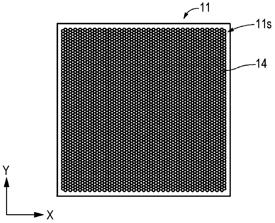
[0062] In the following, reference will be made to Figure 1A to Figure 1C A configuration example of the transparent laminate 11 is described. The transparent laminate 11 includes a surface 11s having an antireflection function. On the surface 11s, fine unevenness is provided. The transparent laminate 11 includes a substrate 12 having a surface and a structural layer 13 disposed on the surface of t...

Deformed example 1

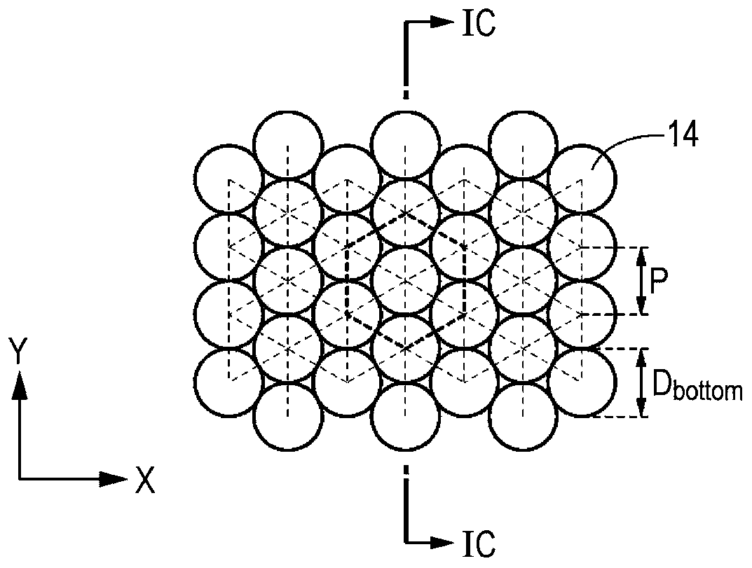
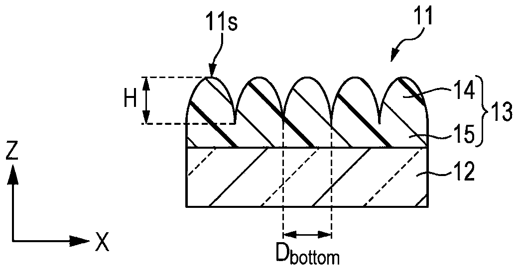
[0120] like Figure 5AAs shown, structure 14 may have a substantially flat top. For example, the plane of the top is substantially parallel to the surface of the substrate 12 . Preferably, the diameter D of the bottom of the structure 14 bottom and the distance P between the structure 14 satisfies 1.2>D bottom / P>1 relationship, and the diameter D of the top of the structure 14 top and the diameter D of the bottom of the structure bottom satisfy 0top / D bottom ≤1 / 10 relationship, and thus excellent anti-reflection performance can be obtained. For example, for the purpose of reducing reflection, the maximum reflectance of the reflective structure layer 13 itself with respect to light may be set to 0.2% or less. Here, 1.2>D bottom / P>1 means that the lower portions of adjacent structures 14 overlap each other. However, when 1.2>D is satisfied bottom / P and the overlap becomes larger, the height of the structures on the surface tends to be lower, and the antireflection p...


PUM

PropertyMeasurementUnit
wavelengthaaaaaaaaaa
thicknessaaaaaaaaaa
wavelengthaaaaaaaaaa

Abstract

There is provided a laminated body, including a substrate and a structure layer which is provided on the substrate and has an anti-reflection function, in which the structure layer includes a plurality of structure bodies and an intermediate layer which is provided between the plurality of structure bodies and the substrate and, in which the intermediate layer satisfies a following relational expression (1). (2&pgr; / λ)·n(λ)·|d−d0|<&pgr; (1) (where, λ represents a wavelength of light for a purpose of reduction of reflection, n(λ) represents a refractive index of the intermediate layer when the wavelength is λ, d0 represents a thickness of the intermediate layer at a center point, and d represents a thickness of the intermediate layer at any point).

Description

[0001] Cross References to Related Applications [0002] This application claims the benefit of Japanese Priority Patent Application JP2013-200327 filed on September 26, 2013, the entire contents of which are hereby incorporated by reference. technical field [0003] The present technology relates to a laminate having an antireflection function, an imaging element package, an imaging device, and an electronic device. Background technique [0004] For glass or films used in displays, camera lenses, etc., various anti-reflection technologies are used to suppress surface reflections. As an antireflection technique, a technique of forming a thin film having a lower refractive index than a surface substrate and a technique of alternately laminating a high-refractive-index material and a low-refractive-index material are generally employed. [0005] However, the anti-reflection technology forms a thin film through a vacuum process such as sputtering, vacuum deposition method, etc...

Claims


Application Information

Patent Timeline
Patent Type & Authority Patents(China)
IPC IPC(8): G02B5/00G02B1/11
CPCG02B1/118
Inventor 田泽洋志林部和弥
Owner SONY CORP
Why Eureka
Try Eureka