Attenuation slice placing device

An attenuator and mounting base technology, applied in the laser field, can solve the problems affecting the beam quality and the interference fringes of the outgoing light spot, and achieve the effect of accurate light spot information, eliminating background and noise, and shielding stray light.

Inactive Publication Date: 2015-01-21
BEIJING GK LASER TECH
View PDF2 Cites 0 Cited by
  • Summary
  • Abstract
  • Description
  • Claims
  • Application Information

AI Technical Summary

Problems solved by technology

However, in actual use, it is found that when this placement method is used, interference fringes often appear in the exit spot, which seriously affects the beam quality

Method used


Image

  • Attenuation slice placing device
  • Attenuation slice placing device
  • Attenuation slice placing device

Examples


Embodiment Construction

[0023] The present invention will be further described below in conjunction with the accompanying drawings and embodiments.

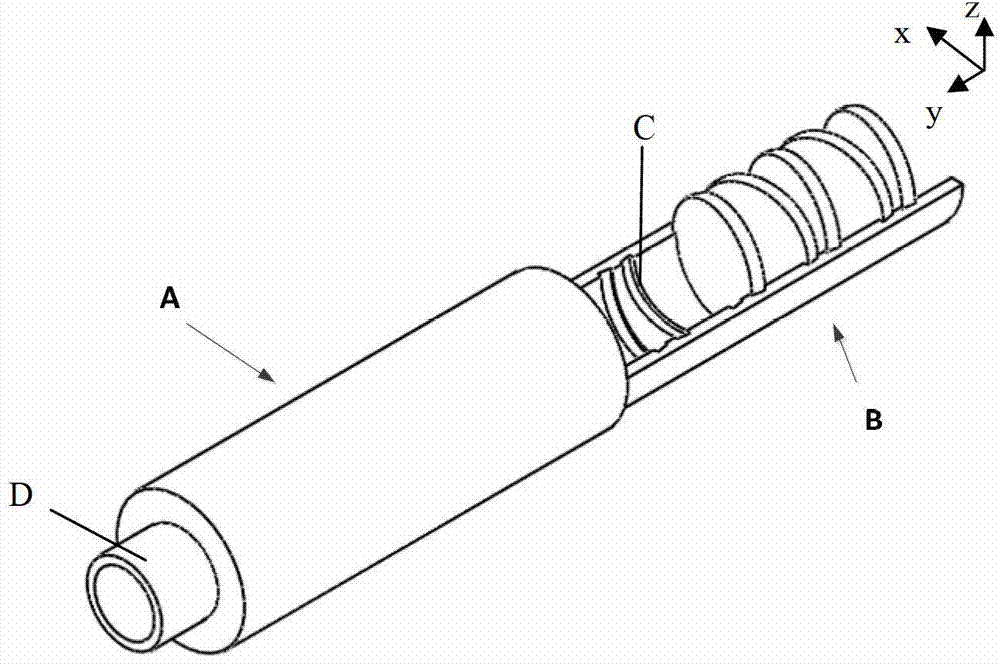
[0024] image 3 A three-dimensional schematic diagram showing an attenuation sheet placement device according to an embodiment of the present invention, such as image 3 As shown, the attenuation sheet placement device includes a sleeve A and a drawer-shaped mounting seat B installed in the sleeve A. The mounting seat B can be drawn out and pushed in along the axis of the sleeve A, so that it can be conveniently quickly replace the attenuator according to actual needs, Figure 4 A three-dimensional schematic view of the installation seat B being pushed into the sleeve A is shown. In one embodiment, along the length direction of the mounting base B, the inner surface of the mounting base B is sequentially provided with multiple (at least two) grooves C for placing attenuation sheets, so that multiple attenuation sheets form a stage couplet. Each groo...


PUM


Abstract

The invention provides an attenuation slice placing device which comprises an installation seat. The attenuation slice placing device is characterized in that at least two grooves for placing attenuation slices are sequentially arranged on the surface of the installation seat along the axis direction, and the grooves are inclined so that each two adjacent attenuation slices are ranked in a splayed shape after the attenuation slices are installed in the grooves. By means of the attenuation slice placing device, interference fringes generated due to exit spots of the attenuation slices are effectively inhibited, the attenuation slices can be rapidly replaced, different attenuation multiples can be flexibly and rapidly matched, the device can be conveniently matched with a charge coupled device (CCD) to form a completely sealed structure, and stray light can be shielded, backgrounds and noises brought by the stray light can be removed, so that collected spot information is accurate.

Description

technical field [0001] The invention relates to the field of laser technology, in particular, the invention relates to a device for placing attenuation sheets. Background technique [0002] There are two main types of traditional attenuation sheet placement devices, one is a cylinder-type placement device, and the other is a wheel-type placement device. Generally speaking, it is often necessary to match the attenuation multiple when setting the attenuator, which requires the attenuator placement device to consider the convenience of replacing the attenuator. If a cylindrical device is used, the device needs to be taken out from the optical path every time the attenuator is replaced, which is very troublesome to operate. The roulette placement device can replace the attenuation sheet by rotating the roulette, and realize the ratio of attenuation multiples to a certain extent. However, the types of attenuation multiples it can provide are limited to the number of attenuation...

Claims


Application Information

Patent Timeline
Patent Type & Authority Patents(China)
IPC IPC(8): G02B7/00G02B27/48
Inventor 樊仲维邱基斯唐熊忻
Owner BEIJING GK LASER TECH
Why Eureka
Try Eureka