
Middle-large size high speed rare-earth permanent magnet motor magnetic steel locking structure

A rare-earth permanent magnet motor, high-speed technology, applied in the direction of magnetic circuit shape/style/structure, magnetic circuit rotating parts, etc., can solve the problems of complex process, performance degradation, poor temperature adaptability, etc., and achieve convenient and simple process operation , the number of parts is small, and the overall cost is low

Active Publication Date: 2015-04-15
安徽明腾永磁机电设备有限公司
View PDF8 Cites 11 Cited by
  • Summary
  • Abstract
  • Description
  • Claims
  • Application Information

AI Technical Summary

Problems solved by technology

[0008] In actual operation and use, there are more or less defects in the various surface-mounted magnetic steel fixing methods in the past, such as: the stability of the adhesive method is poor, and it is impossible to do non-destructive testing, and the firmness and reliability are difficult to guarantee.
Moreover, the high temperature resistance of the glue is poor, such as the more commonly used epoxy glue, when it is close to about 120°C, the performance will drop sharply, so simply using glue to fix the magnetic steel, the temperature adaptability is not good
[0009] Process the threaded holes on the rotor core alone, the strength of the motor is relatively poor when rotating at high speed, and the requirements for the rotor core are high, and the post-processing of the rotor core is complicated
In addition, the interpole pressure plate can only be used on the edge of the magnetic pole. For the magnetic pole of a large motor, it is generally composed of multiple small magnetic steels, and the magnetic pole pressure plate cannot be used.
[0010] The method of adding an external fixed sleeve is complex in process and requires special design of various parts, resulting in complex rotor structure, easy to increase assembly error, and time-consuming and material-consuming processing of each part
[0011] Fiber tape binding method, if the fiber tape is tied thick, it will affect the air gap, and the uniformity of the axial thickness is not easy to ensure; if the fiber tape is tied thin, it is difficult to guarantee the firmness and reliability, and it is easy to loose
The fiber band binding method has poor positioning in the circumferential direction and is easy to move in the circumferential direction
[0012] Binding with metal wires or metal strips can ensure the reliability of the magnetic steel fixing in terms of strength, but the process is complicated, especially when the metal wires or metal strips are damaged, it will inevitably cause damage between the poles of the motor, so long-term reliability is difficult to guarantee

Method used


Image

  • Middle-large size high speed rare-earth permanent magnet motor magnetic steel locking structure
  • Middle-large size high speed rare-earth permanent magnet motor magnetic steel locking structure
  • Middle-large size high speed rare-earth permanent magnet motor magnetic steel locking structure

Examples


Embodiment Construction

[0033] The present invention will be described in further detail below in conjunction with the accompanying drawings and specific embodiments, but not as a limitation of the present invention.

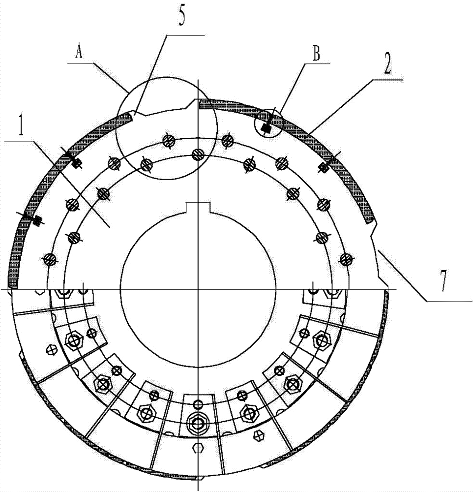
[0034] Such as figure 1 As shown, the rotor structure of the rare earth permanent magnet motor of the present invention includes a rotor core 1 and magnetic poles attached to the outer surface of the rotor core 1. made by splicing.

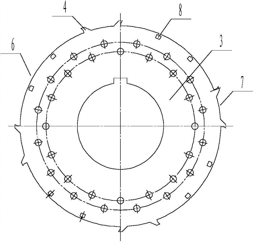
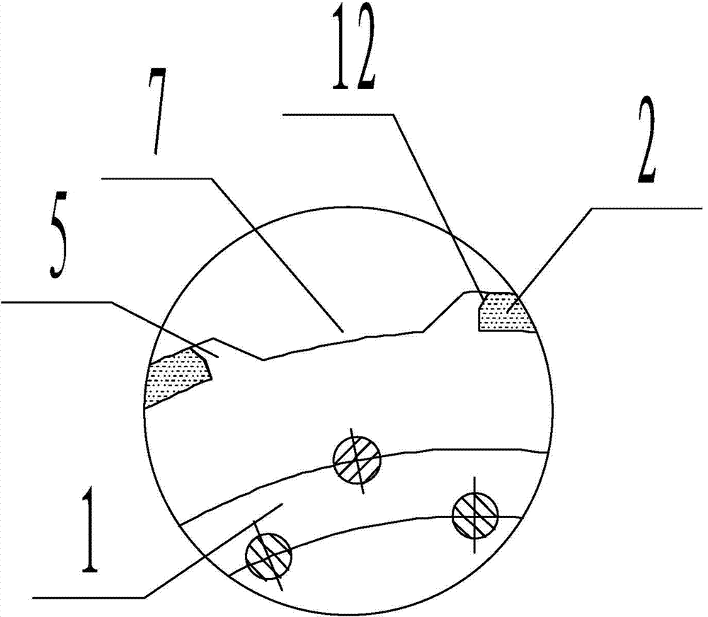
[0035] The rotor core 1 is made of multiple pieces such as figure 2 The rotor punches 3 shown are formed by stacking together. The outer circumference of the rotor punches 3 is provided with a plurality of protrusions 4 and a plurality of T-shaped slots 8 for inserting wedges 9. When multiple rotors are When the punching sheets 3 are stacked together to form the rotor core 1, as figure 1 with image 3 , Figure 4 As shown, a plurality of ribs 5 extending along the axial direction are formed on the outer circumference of the rotor core 1, and the ribs...


PUM


Abstract

The invention discloses a middle-large size high speed rare-earth permanent magnet motor rotor structure comprising a rotor core and magnetic poles attached on an outer surface of the rotor core; an outer periphery of the rotor core is provided with a plurality of flanges extending in an axial direction and used for positioning the magnetic poles in a radial direction and the periphery direction; T type slots are arranged between the flanges; each magnetic pole is formed by splicing a plurality of small magnetic steels on the surface of the rotor core in the axial direction and the periphery direction; the spliced magnetic pole is clamped between two adjacent flanges; the magnetic steels are clamped by a wedge nested in the T type slot; two end faces of the rotor core are provided with stop plates used for positioning the magnetic poles in the axial direction. The magnetic poles of the rare-earth permanent magnet motor are fixed in the radial direction and the periphery direction by the flanges arranged on the outer surface of the rotor core and T type slots and wedges between the flanges; the stop plate can fix the magnetic poles in the axial direction; the magnetic pole spliced by small magnetic steels is stable and firm in a whole; the T type slots and wedges are arranged to well solve the middle-large size motor surface mounting type magnetic steel splicing fixation problems.

Description

technical field [0001] The invention relates to a rare-earth permanent-magnet motor, in particular to a rotor structure of a medium, large, few-pole, and high-speed rare-earth permanent-magnet motor. Background technique [0002] In the design of medium and large-scale few-pole high-speed permanent magnet motors, surface-mounted magnetic poles are often used because the magnetic steel occupies a large space. The fixing methods of surface-mounted magnetic steel are commonly used in the following forms: [0003] 1. Directly glue the magnetic steel to the surface of the rotor core; [0004] 2. Fix the magnetic steel on the surface of the rotor core with screws and pressure plates or with a fixing sleeve; [0005] 3. Bind the magnetic steel on the surface of the rotor core with fiber tape or metal wire or metal tape; [0006] 4. The above fixing methods are used in combination. [0007] For example, the Chinese patent application with the publication number CN102097878A and ...

Claims


Application Information

Patent Timeline
Patent Type & Authority Applications(China)
IPC IPC(8): H02K1/28
CPCH02K1/27
Inventor 孙德全刘带娣徐长山潘克灿刘大宝
Owner 安徽明腾永磁机电设备有限公司
Learn More