Balancing or measuring device

A measuring device and balancing technology, applied in the direction of manufacturing tools, mechanical equipment, chucks, etc., can solve the problems of manufacturing the rotor with the precision of the receiving hole of the base body, sensitive to wear of the centering parts, and crushing of the coupling rod, etc., to achieve high elasticity , Stable rotation centering, improve the effect of stability

Active Publication Date: 2015-04-15
FRANZ HAIMER MASCHINENBAU KG
View PDF5 Cites 2 Cited by
  • Summary
  • Abstract
  • Description
  • Claims
  • Application Information

AI Technical Summary

Problems solved by technology

However, since balancing or measuring devices are also used for tool holders and tools of various manufacturers, and it cannot always be ensured that the rotor is produced in a precise manner with the receiving bore of the base body, ball bushings are used as additional centering elements, for example
However, this centering part is wear-sensitive and can leave undesired crush points or movement marks on the coupling rod

Method used


Image

  • Balancing or measuring device
  • Balancing or measuring device
  • Balancing or measuring device

Examples


Embodiment Construction

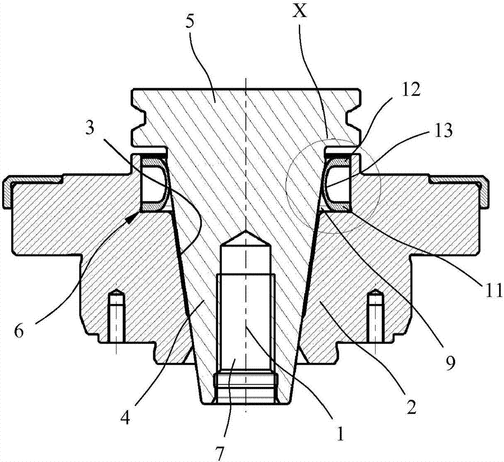
[0037] figure 1 Shown is a base body 2 rotating about an axis of rotation 1 , which includes a conical receiving hole 3 for receiving a coupling rod 4 of a rotor 5 . The rotor 5 can be, for example, a tool holder, a tool or another component to be balanced or measured. Arranged in the base body 2 is an annular centering element 6 for pivotally centering the tool holder 5 within the receiving opening 3 of the base body 2 . The base body 2 and the centering part 6 are components of a balancing or measuring device which are installed in a balancing or measuring machine for balancing or measuring rotating components. In the exemplary embodiment shown, the base body 2 is designed as an adapter for fastening to a machine spindle. As a result, the balancing or measuring device can be adapted relatively quickly and easily to different types of coupling rods on the tool or tool holder. However, base body 2 can also be the motor-driven machine spindle itself.

[0038] The rotor 5 co...


PUM


Abstract

The invention relates to a balancing or measuring device comprising a main body (2) which rotates about an axis of rotation (1) and includes an opening (3) for accommodating a coupling shaft (4) of a rotor (5), and comprising a centering element (6) for centering the rotor (5) in the opening (3). The centering element (6) includes at least one support zone (13, 16, 22, 25, 29) which rests against the coupling shaft (4) and is resilient in the radial direction.

Description

technical field [0001] The invention relates to a balancing or measuring device according to the preamble of claim 1 and to a balancing or measuring machine having such a balancing or measuring device. Background technique [0002] Such balancing and / or measuring machines for balancing or measuring tools, tool holders (tool holders) or other forms of rotors typically include a machine spindle driven by a drive motor, an adapter mountable in the machine spindle or another surrounding A base body, which rotates with the axis of rotation, has a central receiving opening into which a coupling rod of the rotor can be inserted axially. By means of suitable fastening devices, the rotor can be clamped via its coupling rod in the receiving opening of the rotary base body. In order to precisely center the rotor within the base body rotating about the axis of rotation, not only must the receiving bore in the base body be produced with extreme precision, but also the coupling rod must ...

Claims


Application Information

Patent Timeline
Patent Type & Authority Applications(China)
IPC IPC(8): B23B31/117B23B31/00
CPCB23B2231/2097B23B2231/04B23B2270/12B23B31/117B23B31/006B23B2270/06Y10T279/26B23B2265/08
Inventor F·海莫
Owner FRANZ HAIMER MASCHINENBAU KG
Why Eureka
Try Eureka