Connecting structure of vehicle back floor cross beam and longitudinal beams

A technology for connecting structure and rear floor, applied in the directions of superstructure, superstructure sub-assembly, vehicle parts, etc., can solve the problems of low manufacturing precision, large welding influence area, poor rigidity and strength of parts, etc., and achieve high production efficiency , The mold cost is low, and the effect of ensuring reliability

Active Publication Date: 2017-02-15
ZHEJIANG GEELY NEW ENERGY COMML VEHICLES CO LTD +1
View PDF7 Cites 2 Cited by
  • Summary
  • Abstract
  • Description
  • Claims
  • Application Information

AI Technical Summary

Problems solved by technology

[0005] In view of this, the present invention aims to propose a connection structure between the rear floor beam and the longitudinal beam of the automobile, so as to overcome the high cost of mold development of the t

Method used


Image

  • Connecting structure of vehicle back floor cross beam and longitudinal beams
  • Connecting structure of vehicle back floor cross beam and longitudinal beams
  • Connecting structure of vehicle back floor cross beam and longitudinal beams

Examples


Embodiment Construction

[0024] In order to further explain the technical means and functions adopted by the present invention to achieve the intended invention purpose, the specific implementation, structure, features and functions of the present invention will be described in detail below in conjunction with the accompanying drawings and preferred embodiments.

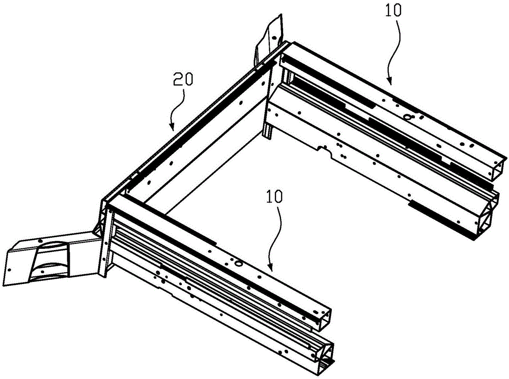
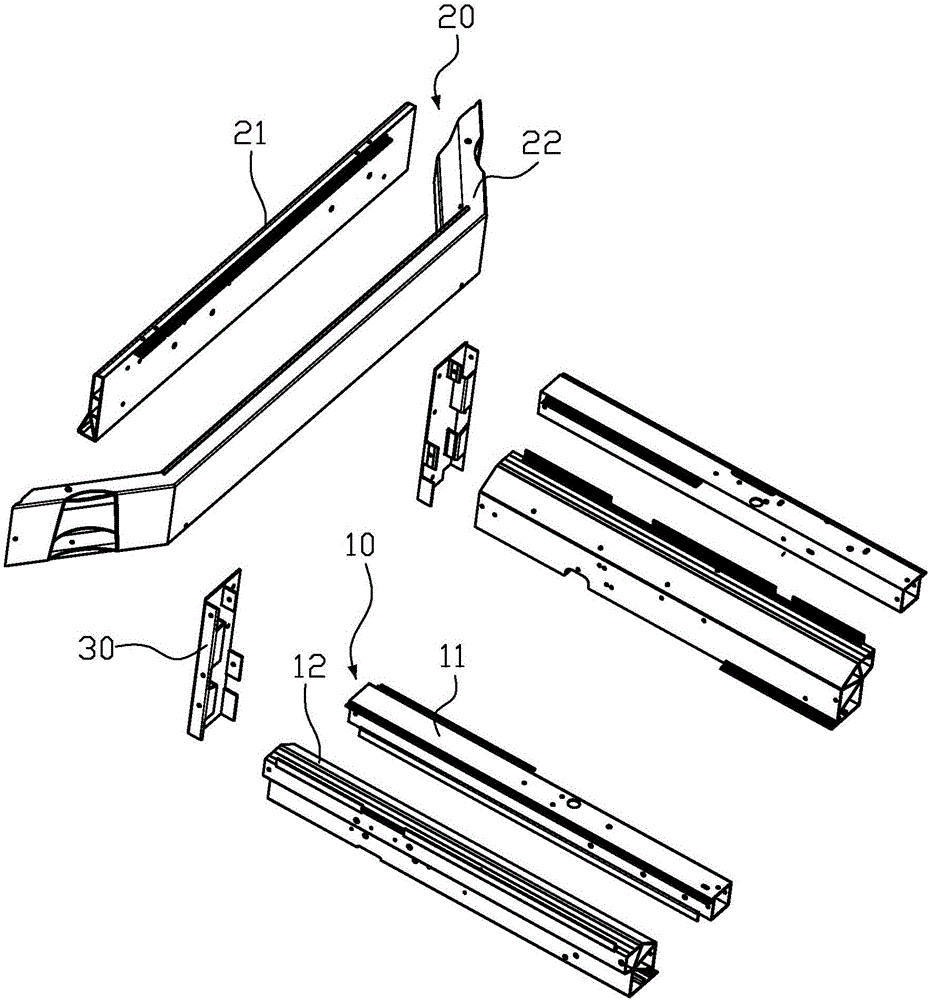
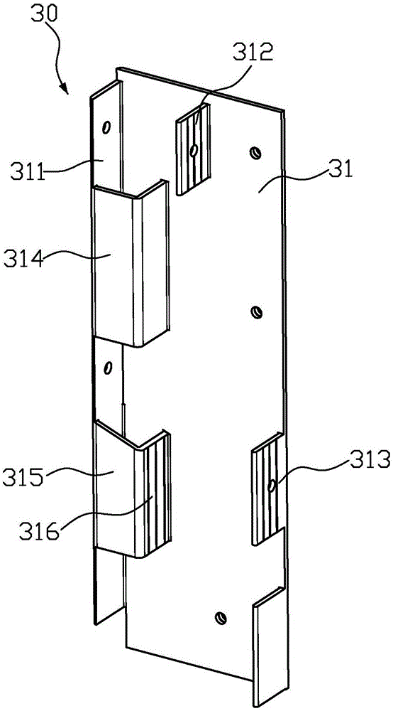
[0025] figure 1 It is a schematic diagram of the assembly of the rear floor beam and the longitudinal beam of the connection structure between the rear floor beam and the longitudinal beam of the automobile provided by the embodiment of the present invention, figure 2 for figure 1 Schematic diagram of the decomposition structure of the middle and rear floor beams and longitudinal beams, image 3 Schematic diagram of the connecting bracket. Please refer to Figure 1 to Figure 3 , a connection structure between rear floor beams and longitudinal beams of an automobile, comprising two rear floor longitudinal beams 10 and a rear floor beam 20...


PUM


Abstract

The invention proposes a connecting structure of a vehicle back floor cross beam and longitudinal beams. The connecting structure comprises the back floor cross beam and two back floor longitudinal beams; the two back floor longitudinal beams are fixedly connected with the back floor cross beam through connecting brackets; the connecting brackets include connecting plates as support bodies; connecting plate surfaces are arranged at the front ends of the connecting plates for gluing with the back floor cross beam; multiple connecting parts are formed on the back surfaces of the connecting plates; and the connecting parts are glued with the back floor longitudinal beams. The unique structure design of the connecting brackets realizes large-area gluing of the front ends of the connecting brackets and the back floor cross beam and one-way and two-side connection of the back ends of the connecting brackets and the back floor longitudinal beams so as to realize connection of profile cross beams and longitudinal beams and guarantee the connecting reliability; aluminum alloy profiles with better rigidity and strength are adopted; profile molds are lower in cost; and the production efficiency is high. As a structural glue bonding process is adopted, the strength of a gluing area is not influenced, the self manufacturing errors of parts and assembly errors among the parts can be eliminated, and the manufacturing precision is improved.

Description

technical field [0001] The invention relates to a connection structure between auto parts, in particular to a connection structure between a rear floor beam and a longitudinal beam of an automobile. Background technique [0002] As the all-aluminum body technology is becoming more and more popular in the market, the connection between the floor longitudinal beam and the beam of the all-aluminum body model mainly includes two connection methods: the overlapping of aluminum sheet stamping parts or the overlapping of profile parts and cast aluminum parts. The way in which the stamped parts of aluminum plate are overlapped with each other, the main parts in this combination method are all stamped and formed, and the longitudinal beams and beams are connected by spot welding, welding or riveting of the parts. As for the overlapping connection of profile parts and cast aluminum parts, the beam is a profile part and the rear longitudinal beam of the floor is a cast aluminum part in...

Claims


Application Information

Patent Timeline
IPC IPC(8): B62D25/20
CPCB62D25/20
Inventor 陈春龙陈君张之好黄艳灵陈志恒汪万松李红艳
Owner ZHEJIANG GEELY NEW ENERGY COMML VEHICLES CO LTD
Why Eureka
Try Eureka