Transmission system
一种影像信号、发送装置的技术,应用在传输系统、数字传输系统、基带系统等方向,能够解决信号传输困难等问题,达到稳定帧速率、抑制发热的效果
- Summary
- Abstract
- Description
- Claims
- Application Information
AI Technical Summary
Problems solved by technology
Method used
Image
Examples
no. 1 Embodiment approach
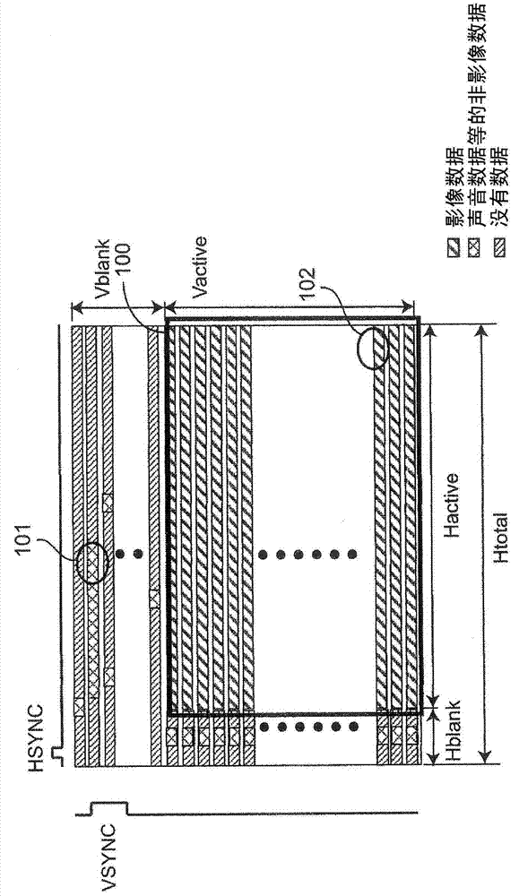
[0037] Figure 1A It is a diagram showing a frame format at the time of data transmission according to the first embodiment of the present disclosure. exist Figure 1A Among them, HSYNC represents the horizontal synchronization signal, and VSYNC represents the vertical synchronization signal. In addition, Vblank represents a vertical blanking period, and Hblank represents a horizontal blanking period. The period of Vblank or Hblank is a blanking period for transmitting non-image data. Non-video data is, for example, audio data and / or control data. Furthermore, Vactive represents a period other than the above-mentioned vertical blanking period, and Hactive represents a period other than the above-mentioned horizontal blanking period. The period of Vactive and Hactive is an active period for transferring video data.
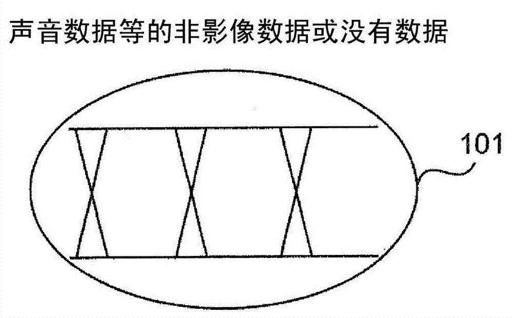
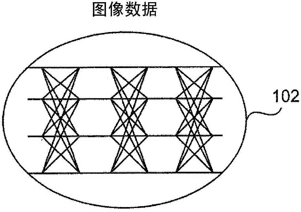
[0038] Figure 1B yes means Figure 1A The binary-valued transmit signal 101 of the blanking period ( Figure 1A ) waveform diagram, Figure 1C yes means Fig...
no. 2 Embodiment approach
[0059] Figure 3A It is a block diagram showing the configuration of a transmission device 1A of a transmission system using the multilevel amplitude modulation method according to the second embodiment of the present disclosure. Figure 3A The transmission device 1A according to the second embodiment shown and Figure 2A Compared with the transmission device 1 according to the first embodiment shown, there are the following differences.
[0060] (1) The non-video signal generation unit 11 is Figure 2A A 1-bit non-image signal is generated in the Figure 3A A non-image signal of a × 1 bit is generated in it. Here, a is plural, and the following is the same. However, the case where a is 1 is the above-mentioned first embodiment.
[0061] (2) The video signal generator 12 is Figure 2A A plurality of N-bit image signals are generated in the Figure 3A A video signal of a×N bits is generated in the system.
[0062] (3) replace Figure 2A The binary signal generator 17 p...
no. 3 Embodiment approach
[0081] Figure 4 It is a diagram showing the frame format of transmission data according to the third embodiment of the present disclosure. exist Figure 4 Among them, it is characterized in that a transmission signal with a small multi-valued number is transmitted during a vertical blanking period 300b, which is a part of the blanking period, and a multi-valued number larger than that in the vertical blanking period 300b is transmitted in a period 300a other than the vertical blanking period 300b. A send signal of a multivalued number is transmitted.
[0082] Figure 5A It is a block diagram showing the configuration of a transmission device 1B of a transmission system using the multilevel amplitude modulation method according to the third embodiment of the present disclosure. Figure 5A The sending device 1B is shown with Figure 3A Compared with the transmission device 1A according to the third embodiment shown, the following points are different.
[0083] (1) In place...
PUM
 Abstract
Description
Claims
Application Information
 - R&D
- Intellectual Property
- Life Sciences
- Materials
- Tech Scout
- Unparalleled Data Quality
- Higher Quality Content
- 60% Fewer Hallucinations
Browse by: Latest US Patents, China's latest patents, Technical Efficacy Thesaurus, Application Domain, Technology Topic, Popular Technical Reports.
© 2025 PatSnap. All rights reserved.Legal|Privacy policy|Modern Slavery Act Transparency Statement|Sitemap|About US| Contact US: help@patsnap.com


