
ecu for vehicle

A microcomputer and pre-disconnection technology, applied in vehicle components, instruments, electrical digital data processing, etc., can solve the problems of power consumption, dark current increase, battery fuel consumption increase, deterioration, etc., to achieve low power consumption, Realize the effect of the device structure

Inactive Publication Date: 2016-11-02
AUTONETWORKS TECH LTD +2
View PDF5 Cites 0 Cited by
  • Summary
  • Abstract
  • Description
  • Claims
  • Application Information

AI Technical Summary

Problems solved by technology

In order to drive these microcomputers, power consumption and dark current increase, which is one of the reasons for the increase of batteries and the deterioration of fuel consumption.

Method used


Image

  • ecu for vehicle
  • ecu for vehicle
  • ecu for vehicle

Examples


Embodiment approach 1

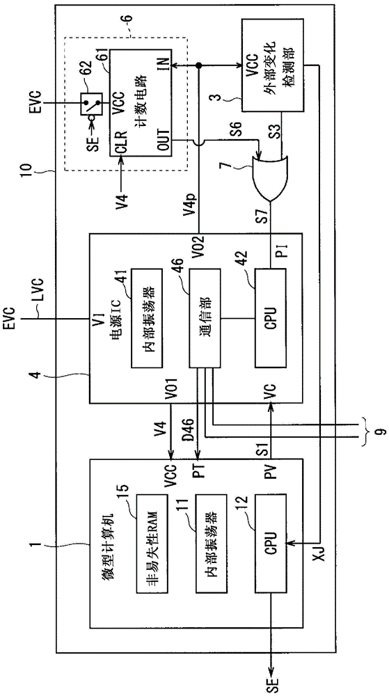
[0033] figure 1 It is a block diagram showing the internal configuration of the vehicle-mounted ECU according to Embodiment 1 of the present invention. The vehicle-mounted ECU 10 according to the first embodiment includes a microcomputer 1 , an external change detection unit 3 , a power supply IC 4 , a counting unit 6 , and an OR gate 7 .

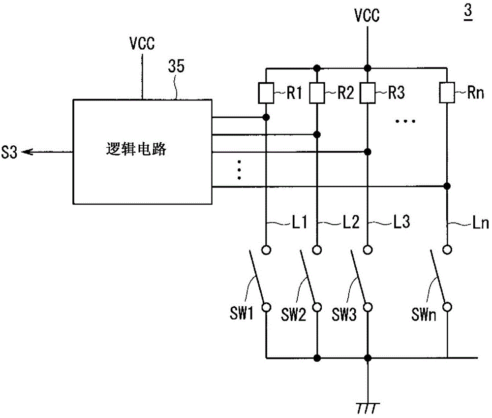
[0034] The microcomputer 1 has an internal oscillator 11, a CPU 12, and a nonvolatile RAM 15 inside. The microcomputer 1 is in an operating state when the operating power supply V4 is supplied to the power input unit VCC, and in the operating state, the CPU 12 operates with a clock generated by the internal oscillator 11, and receives information as the state of the switches (groups) in the external change detection unit 3. External input information XJ.

[0035] Then, when the CPU 12 detects (generation of) an external input from any of the switch groups based on the external input information XJ, it performs predetermined operation cont...

Embodiment approach 2

[0106] Figure 9 It is a block diagram showing an internal configuration of an in-vehicle ECU according to Embodiment 2 of the present invention. The vehicle-mounted ECU 20 according to Embodiment 2 internally includes a microcomputer 1 , an external change detection unit 3 , and a power supply IC 5 . The microcomputer 1 , external change detection unit 3 , and internal oscillator 41 , CPU 42 , and communication unit 46 in the power supply IC 5 are the same as those in Embodiment 1, and therefore are denoted by the same reference numerals and descriptions thereof are appropriately omitted. Below, with figure 1 The differences of the vehicle-mounted ECU 10 according to the first embodiment shown will be mainly described.

[0107] The external change detection unit 3 is different from the first embodiment in that the detection signal S3 is directly output to the input terminal PI of the power supply IC5.

[0108]The counting circuit 63 is built in the power supply IC 5, and u...


PUM


Abstract

An object of the present invention is to obtain an in-vehicle ECU capable of minimizing power consumption when an internal microcomputer does not need to operate. Furthermore, in the present invention, when the power supply IC (4) is in the pre-off mode, the supply of the operating power (V4) from the power output unit (VO1) is stopped, and when the OR gate output signal (S7) is "H", The supply of the operating power supply (V4) to the microcomputer (1) is restarted. The CPU (12) in the microcomputer (1) recognizes that the non-occurrence is based on the presence or absence of time-dependent changes in the external input information (XJ) when the supply of the operating power (V4) after the pre-off mode is set is restarted. When a predetermined time elapses from the setting of the pre-disengagement mode as the activation factor of the microcomputer (1) changes, in order to execute the power supply stop operation of stopping the power supply to the power control target ECU, output "H" Power control signal (SE).

Description

technical field [0001] The present invention relates to a vehicle-mounted ECU (Electronic Control Unit, electronic control unit) mounted on a vehicle. Background technique [0002] Conventionally, a vehicle is equipped with a plurality of electronic devices called in-vehicle ECUs, and each in-vehicle ECU exchanges information and coordinates operations through a network such as CAN (Controller Area Network, Controller Area Network), thereby realizing the functions related to the driving of the vehicle. Controls and controls related to comfort in the vehicle interior and the like. Each of the vehicle-mounted ECUs is connected to a power source such as a battery or an alternator of the vehicle via a power line, and operates with electric power supplied from the power source. In recent years, the number of in-vehicle ECUs mounted in vehicles has increased, and power saving has been pursued. [0003] Furthermore, as vehicles become more functional, a large number of highly fun...

Claims


Application Information

Patent Timeline
Patent Type & Authority Patents(China)
IPC IPC(8): B60R16/02
CPCH02J9/005G06F1/3206G06F1/3287G06F1/3228H02J2310/46Y02D10/00G06F1/3203B60R16/03
Inventor 渡边章代
Owner AUTONETWORKS TECH LTD
Learn More