Gas stirring tank easy to heat and stirring method

A technology of gas stirring and stirring tank, which is applied in the direction of mixer accessories, chemical instruments and methods, dissolution, etc., can solve the problems of no heating device, uneven stirring, and inability to heat materials, so as to save production equipment, improve heating efficiency, The effect of saving production space

Inactive Publication Date: 2015-04-22
SHANDONG JIN ZELI ENERGY TECH
View PDF6 Cites 9 Cited by
  • Summary
  • Abstract
  • Description
  • Claims
  • Application Information

AI Technical Summary

Problems solved by technology

However, on the one hand, the stirred reactor does not stir evenly, and on the other hand, it does not involve a heating device, so it cannot realize the heating function for the materials at the same time.

Method used


Image

  • Gas stirring tank easy to heat and stirring method
  • Gas stirring tank easy to heat and stirring method

Examples


Embodiment 1

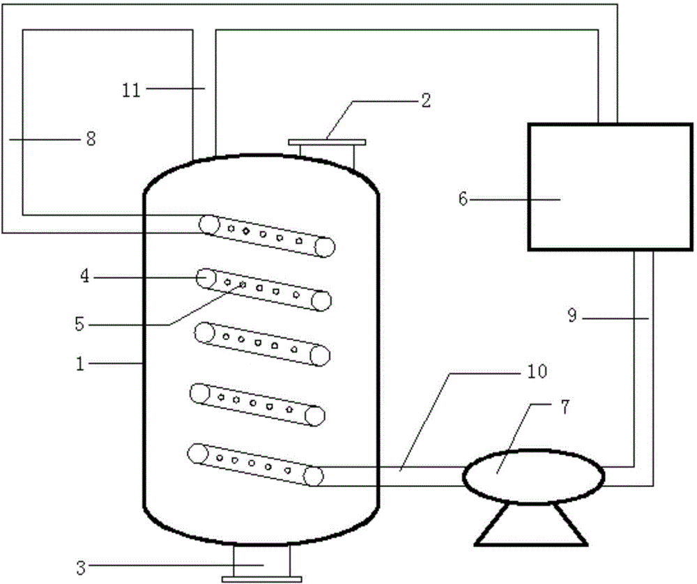
[0024] A gas stirred tank that is easy to heat includes a stirred tank body 1, a heating furnace 6 and an air blowing device 7 for intermittently blasting the stirred tank body 1. The top of the stirred tank body 1 is provided with a feed port 2, The bottom of the stirred tank body 1 is provided with a discharge port 3, and the inside of the stirred tank body 1 is uniformly provided with a coil 4 from the bottom end to the top, and the coil 4 is uniformly provided with an air injection hole 5 The outlet of the coiled pipe 4 is connected to the heating furnace 6 through the first connecting pipe 8, and the heating furnace 6 is connected to the blowing device 7 through the second connecting pipe 9, and the described blowing device 7 is passed through the third The connecting pipe 10 is connected to the inlet of the coil pipe 4 ; the top of the stirred tank body 1 communicates with the first connecting pipe 8 through the fourth connecting pipe 11 .

[0025] The blowing device 7 d...

Embodiment 2

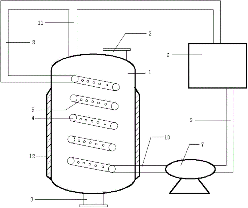
[0029] Easy-to-heat gas stirred tank as described in Example 1, the difference is that the outside of the stirred tank body 1 is provided with a jacket 12;

[0030] The blast device 7 is a compressor, and the duration of each blast is 2 minutes, and the time interval between two adjacent blasts is 30 seconds.

[0031] Since the jacket 12 is provided, the stirred tank has the function of heat preservation, and the heating efficiency is improved.

Embodiment 3

[0033] A kind of method that material is stirred, comprises using the easy-to-heat gas stirred tank described in embodiment 1, and step is as follows:

[0034] Put the material into the stirring tank body 1, turn on the heating furnace 6 and the blower device 7, the heating furnace 6 heats the air and blows the heated air into the coil 4 through the blower device 7, and the heated air passes through the coil The air injection hole 5 set on the pipe 4 is sprayed into the stirring tank body 1 to heat the material; the blower device 7 performs intermittent blasting, and the material spirally rises under the action of the heated air sprayed from the air injection hole 5 to form Vortex, and then realize the stirring effect on the material.


PUM


Abstract

The invention relates to a gas stirring tank easy to heat and a stirring method. The gas stirring tank comprises a stirring tank body, a heating furnace, and a blower device for intermittent blowing the stirring tank body; a feed inlet is disposed at the top end of the stirring tank body; a discharge port is disposed at the bottom end of the stirring tank body; a coil pipe is uniformly disposed inside the stirring tank from bottom to top; blowholes are uniformly disposed on the coil pipe; an outlet of the coil pipe is connected with the heating furnace through a first connecting pipe; the heating furnace is connected with the blower device through a second connecting pipe; the blower device is connected with an inlet of the coil pipe through a third connecting pipe; the top end of the stirring tank body is communicated with the first connecting pipe through a fourth connecting pipe. The gas stirring tank of the invention realizes stirring and heating processes simultaneously, saves unit operation, and saves production land occupation and production equipment; the gas stirring tank has a simple structure, needs no stirring motor or stirring paddle, and is convenient to operate.

Description

technical field [0001] The invention relates to an easy-to-heat gas stirring tank and a stirring method, belonging to the technical field of stirring equipment. Background technique [0002] The operation of stirring unit is usually involved in the chemical production process, and there are various forms of stirring. However, most of them are in the form of stirring paddles, which not only need to be driven by a motor, but also the equipment is complicated and heavy. Many production raw materials require a heating process, and the heating process often requires a separate heating unit to operate, which not only occupies more production equipment, but also occupies more production sites and increases production costs. [0003] Chinese patent document CN 203417676 U (application number: 201320150794.0) discloses an automatic stirring reaction kettle, including a kettle body, a feed inlet, an exhaust system, an air supply pipe, an air supply system, a discharge outlet, an air s...

Claims


Application Information

Patent Timeline
Patent Type & Authority Applications(China)
IPC IPC(8): B01F13/02B01F15/06B01F33/40
Inventor 王昱力王玉峰白逢芳张西收陈天春
Owner SHANDONG JIN ZELI ENERGY TECH
Why Eureka
Try Eureka