
Line drawing method and line drawing tool for on-site assembly

A technology for on-site assembly and line-drawing tools, applied in manufacturing tools, workshop equipment, etc., can solve problems such as low work efficiency and many scrapped parts, and achieve the effects of reducing scrap rate, easy operation, and improving fit

Inactive Publication Date: 2016-11-09
JIANGSU A STAR AVIATION IND
View PDF6 Cites 0 Cited by
  • Summary
  • Abstract
  • Description
  • Claims
  • Application Information

AI Technical Summary

Problems solved by technology

[0004] In order to solve the technical problems of low on-site assembly work efficiency and many scrapped parts in the prior art, the present invention provides an on-site line drawing method and a tool for drawing lines that can greatly improve work efficiency and basically have no scrapped parts

Method used


Image

  • Line drawing method and line drawing tool for on-site assembly
  • Line drawing method and line drawing tool for on-site assembly

Examples


Embodiment Construction

[0017] The present invention is described below in conjunction with accompanying drawing:

[0018] A line-drawing method for field assembly comprising the following steps:

[0019] A. Cutting and rough machining: Preliminary cutting of the assembly 8 and rough machining;

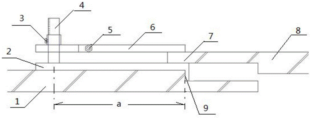
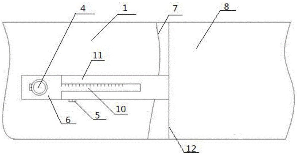
[0020] B. Positioning of the contact surface 9: install and fix the mounting part 1, and determine the position of the curved surface on the mounting part 1 that is in contact with the assembly part 8 as the contact surface 9;

[0021] C. Semi-fixing the assembly part 8: fix the positioning end of the assembly part 8 in step A, and lap the grinding end 7 on the surface of the mounting part 1;

[0022] D. Draw a line on the mounting part 1: Use one side of the square to clip on the contact surface 9 of the mounting part 1, and the other side of the square to overlap the mounting part 1, and the mounting part 1 with a fixed distance a from the square Draw a point on the top, and the inner surface of the shor...


PUM


Abstract

A line drawing method for field assembling comprises the first step of discharging and rough machining, the second step of contact face positioning, the third step of half-fixing of an assembly piece, the fourth step of transition line drawing on an installing piece, the fifth step of cutting line drawing on the assembly piece and the sixth step of grinding. A line drawing tool for field assembling comprises a ranging ruler, a line drawing ruler and a connecting shaft. The ranging ruler comprises a limiting body and a ruler body. The limiting body is connected with one end of the ruler body, and a right angle is formed between the limiting body and the ruler body. The other end of the ruler body is fixedly installed on the connecting shaft. One end of the line drawing ruler is installed on the connecting shaft. The ranging ruler and the line drawing ruler are perpendicular to the connecting shaft in the same direction. The distance between the other end of the line drawing ruler and the axis of the connecting shaft is matched with the distance between the inner side surface of a limiting step of the ranging ruler and the axis of the connecting shaft. According to the line drawing method and the line drawing tool, the component scrappage can be reduced, and the matching degree of the installing piece and the assembly piece is improved. The line drawing method is simple, and the special line drawing tool is easy to operate. High application value is achieved.

Description

technical field [0001] The invention belongs to the technical field of mechanical manufacturing, and in particular relates to a line-drawing method and a line-drawing tool used when assembling thin-walled parts on site. Background technique [0002] At present, in the field of mechanical manufacturing technology, due to the accumulation of work differences and the adjustment of clearances, some parts, especially thin-walled parts, usually need to be manually cut and polished by the operator according to the on-site assembly situation. However, during the cutting and grinding process, Workers cannot accurately determine the position of cutting and grinding, and can only compare cutting and grinding again and again. In the field of aviation manufacturing technology, this problem is particularly prominent. For example, the assembly accuracy of aircraft skins and fairings is high, and the Occasionally, if the gap between the fairing and the skin is too large, it will affect the ...

Claims


Application Information

Patent Timeline
Patent Type & Authority Patents(China)
IPC IPC(8): B25H7/04
CPCB25H7/04B25H7/045
Inventor 王洪亮孙海波李敬超于天池
Owner JIANGSU A STAR AVIATION IND
Learn More