Forced demoulding device for injection molds

A technology of forced demoulding and injection mold, applied in the field of injection mold manufacturing, can solve problems such as troublesome operation and increased workload

Pending Publication Date: 2015-04-22
DINGSHENG CORP
View PDF11 Cites 4 Cited by
  • Summary
  • Abstract
  • Description
  • Claims
  • Application Information

AI Technical Summary

Problems solved by technology

Now in order to achieve the purpose of fast demoulding, it is necessary to set up a demoulding mechanis

Method used


Image

  • Forced demoulding device for injection molds

Examples


Embodiment Construction

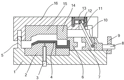
[0013] The present invention will be further described in detail below in conjunction with the accompanying drawings by means of specific embodiments:

[0014] Such as figure 1 The shown injection mold forced demoulding device comprises a patrix 16, a lower die 1, a demoulding module and a demoulding swing lever 11, and the patrix and the patrix are fixedly provided with a patrix insert 15 and The lower mold insert 2, the lower mold 1 is provided with an injection gun 3 leading into the cavity, the stripping module includes a positioning block 6 and a sliding block 7, and the upper mold 16 is provided with a stopper 14 that resists the horizontal direction of the lower mold 1. One end of the mold swing rod 11 is hinged on the upper mold 16, and the other end is hinged on the sliding block 7, and a swing stroke groove is arranged on the upper mold 16 and the sliding block 7, the positioning block 6 and the lower mold 1 are fixed, and the lower mold 1 is provided with Vertical ...


PUM


Abstract

The invention relates to the field of injection mold manufacturing, and particularly relates to a forced demoulding device for injection molds. The forced demoulding device comprises an upper die, a lower die, a demoulding block and a demoulding swing-rod, wherein an upper die insert and a lower die insert which are matched to form an injection part cavity are respectively fixedly arranged in the upper die and the lower die, the lower die is provided with an injection gun extending to the cavity, the demoulding block comprises a positioning block and a slide block, the upper die is provided with a stop dog which is pressed against the horizontal direction of the lower die, one end of the demoulding swing-rod is hinged with the upper die, the other end of the demoulding swing-rod is hinged on the slide block, a swing travel slot is arranged on the upper die and the slide block, the positioning block and the lower die are fastened, the lower die is provided with a vertical sliding pin, the upper die is provided with a pin slot matched with the sliding pin, and the slide block is fixedly connected with a power shaft. The forced demoulding device disclosed by the invention has the beneficial effect that in the process of demoulding, the upper die does not produce an extrusion force on injection parts of injection molds so as to ensure the completeness of the injection parts.

Description

technical field [0001] The invention belongs to the field of injection mold manufacturing, in particular to a forced demoulding device for injection molds. Background technique [0002] Injection mold is an important process equipment for the production of various industrial products. With the rapid development of the plastics industry and the promotion and application of plastic products in aviation, aerospace, electronics, machinery, ships and automobiles and other industrial sectors, injection molds are widely used in various industries middle. The traditional injection mold consists of a moving mold and a lower mold. The moving mold is installed on the moving template of the injection molding machine, and the lower mold is installed on the solid lower template of the injection molding machine. During injection molding, the movable mold and the lower mold are closed to form the gating system and the cavity, and the movable mold and the lower mold are separated to take ou...

Claims


Application Information

Patent Timeline
IPC IPC(8): B29C45/26B29C45/40
CPCB29C45/26B29C45/40
Inventor 胡佐林
Owner DINGSHENG CORP
Why Eureka
Try Eureka