Four-wheel drive axle for obstacle-crossing vehicle
A technology of four-wheel drive and driving axle, which is applied in the direction of wheels, axles, vehicle parts, etc., can solve the problems of low obstacle-crossing ability of obstacle-crossing vehicles and difficult vehicles to cross, and achieve stable and reliable obstacle-crossing performance, long service life, and off-road The effect of high performance
- Summary
- Abstract
- Description
- Claims
- Application Information
AI Technical Summary
Problems solved by technology
Method used
Image

Examples
Embodiment Construction
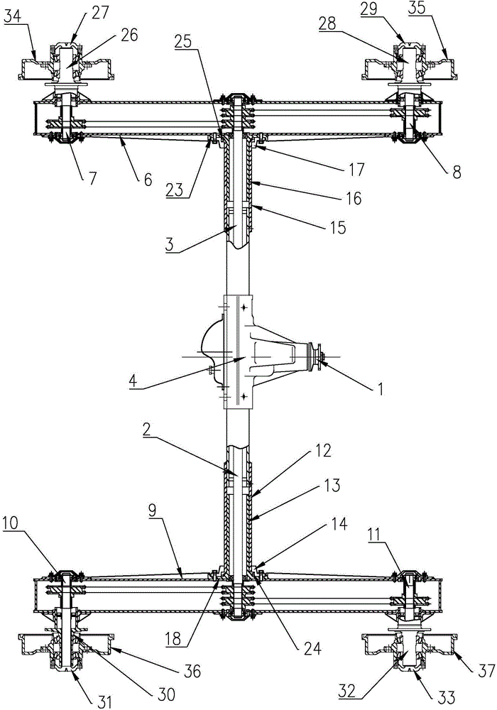
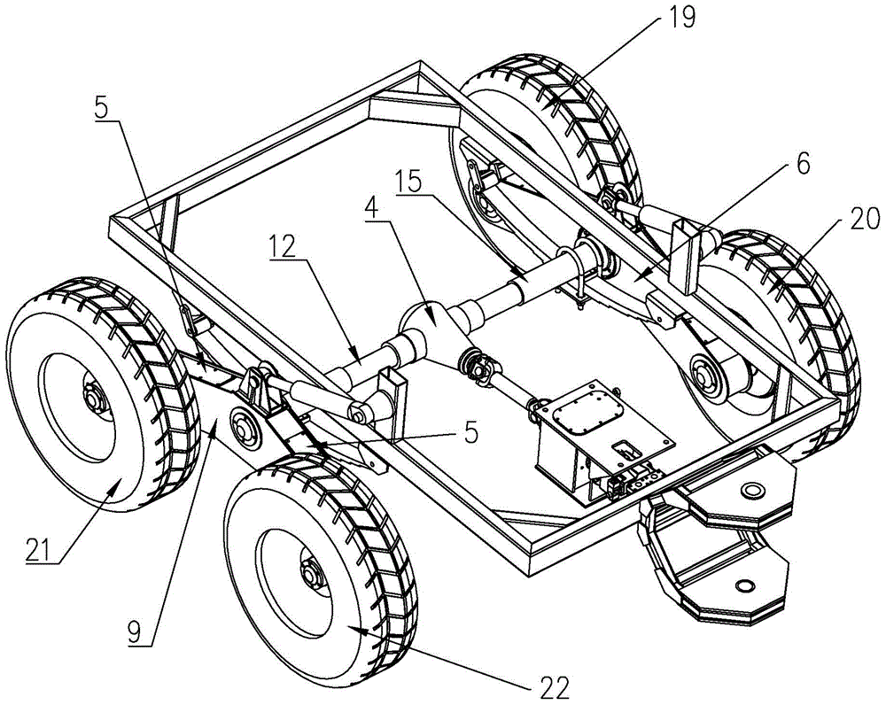
[0021] Such as figure 1 and figure 2 As shown, the four-wheel drive axle for obstacle-crossing vehicles of the present invention includes a drive axle housing 4, a left output shaft 2 and a right output shaft 3, and the left output shaft 2 is installed on the left side in the drive axle housing 4 along the left-right direction. , the right output shaft 4 is installed on the right side in the drive axle housing 4 along the left-right direction. In use, the power input shaft 1 can drive the left output shaft 2 and the right output shaft 3 to rotate.
[0022] The right end of the drive axle housing 4 is provided with a right swing beam 6 along the front and rear direction, the right swing beam 6 is made of steel or aluminum alloy, and the middle part of the right swing beam 6 is rotatably connected to the right end of the drive axle housing 4 , the right output shaft 3 extends to the right to the right swing beam 6, the shaft section of the right output shaft 3 located at the ...
PUM
 Abstract
Description
Claims
Application Information
 - R&D
- Intellectual Property
- Life Sciences
- Materials
- Tech Scout
- Unparalleled Data Quality
- Higher Quality Content
- 60% Fewer Hallucinations
Browse by: Latest US Patents, China's latest patents, Technical Efficacy Thesaurus, Application Domain, Technology Topic, Popular Technical Reports.
© 2025 PatSnap. All rights reserved.Legal|Privacy policy|Modern Slavery Act Transparency Statement|Sitemap|About US| Contact US: help@patsnap.com