Ship and method for transportation and installation of complete offshore wind turbine

A technology for offshore wind turbines and installation methods, which is applied to barges/flat-bottomed boats, etc., and can solve problems such as high construction risks, long offshore construction periods, and high installation costs of offshore wind turbines

Active Publication Date: 2017-09-22
CHINA ENERGY ENG GRP GUANGDONG ELECTRIC POWER DESIGN INST CO LTD
View PDF6 Cites 0 Cited by
  • Summary
  • Abstract
  • Description
  • Claims
  • Application Information

AI Technical Summary

Problems solved by technology

[0002] At this stage, the installation of offshore wind turbines at home and abroad generally adopts a split installation method. Most of the installation ships are self-elevating offshore operation platforms, and there are also a small number of engineering cases where wind turbines are installed integrally. The installation of offshore wind turbines is greatly affected by marine hydrometeorological conditions. The main influencing factors are water depth, wind, waves, rain, fog, thunderstorm and tide, etc. The main disadvantage of the split installation method of offshore wind turbines is that the offshore construction period is long and the construction risk is high; if the offshore wind turbine installation adopts the integral wind turbine installation method, then It can reduce the working time at sea and reduce the uncontrollable risks caused by natural factors. Large-scale crane ships are often used at home and abroad for the installation of integral wind turbines. At the same time, they are equipped with dedicated wind turbine transport ships and tugboats. high cost

Method used


Image

  • Ship and method for transportation and installation of complete offshore wind turbine
  • Ship and method for transportation and installation of complete offshore wind turbine
  • Ship and method for transportation and installation of complete offshore wind turbine

Examples


Embodiment Construction

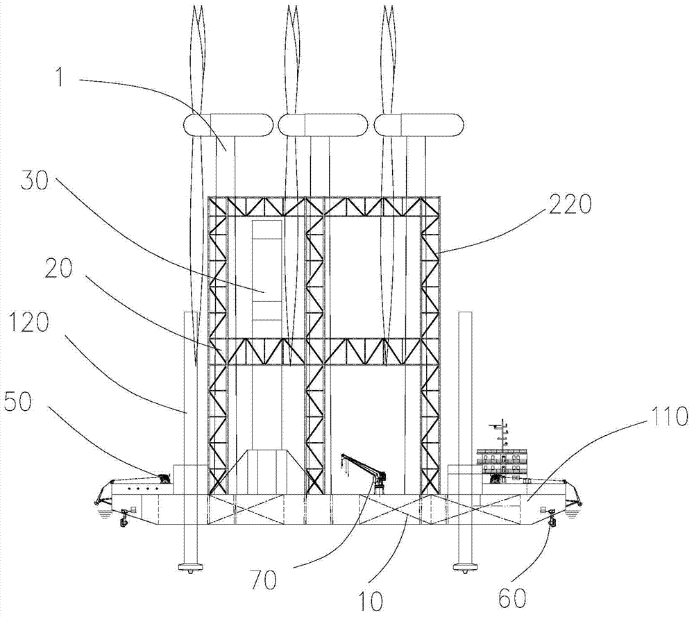
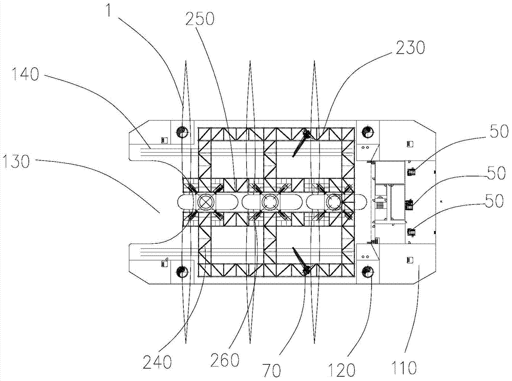
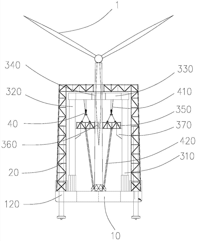
[0034] like Figures 1 to 5 As shown, a special ship for the transportation and installation of offshore wind turbines includes a transport barge 10, a fixed steel frame 20, and a mobile steel frame 30. The transport barge 10 includes a main hull 110 and a cockpit arranged on the main hull 110. and the control system, the main hull 110 is provided with a plurality of self-elevating piles 120, the fixed steel frame 20 is fixedly installed on the main hull 110, and the fixed steel frame 20 is provided with a plurality of first fan hoop mechanisms 210, the moving steel frame is slidably arranged under the fixed steel frame 20, and the moving steel frame includes a first outrigger 310 and a second outrigger 320 oppositely arranged on both sides of the main hull 110, the first outrigger 310 and the second outrigger The upper end of the leg 320 is provided with a spanning support beam 330, the middle part of the support beam 330 is provided with a second fan hoop mechanism 340, and ...


PUM


Abstract

The invention discloses a ship and a method for transporting and installing a complete offshore wind turbine. The special ship for transporting and installing a complete offshore fan includes a transport barge, a fixed steel frame, and a mobile rigid frame. The main hull of the transport barge is equipped with Multiple self-elevating piles, multiple first fan hoop mechanisms are installed on the fixed steel frame, the movable steel frame is slidably arranged under the fixed steel frame, and the mobile steel frame includes the first outriggers arranged oppositely on both sides of the main hull With the second outrigger, the upper ends of the first outrigger and the second outrigger are provided with a supporting beam spanning, the middle part of the supporting beam is provided with a second fan hoop mechanism, and the lower end surface of the supporting beam is provided with a sliding track, and the sliding track There is a lifting mechanism on the top, a balance hanger is arranged under the support beam, a third fan hoop mechanism is arranged on the balance hanger, the lifting mechanism is connected with the balance hanger, and the stern of the main hull is provided with a fan installation notch. It can realize the overall transportation and installation functions of the fan at the same time, effectively reducing costs.

Description

technical field [0001] The invention relates to a special ship and method for transporting and installing an offshore wind turbine. Background technique [0002] At this stage, the installation of offshore wind turbines at home and abroad generally adopts a split installation method. Most of the installation ships are self-elevating offshore operation platforms, and there are also a small number of engineering cases where wind turbines are installed integrally. The installation of offshore wind turbines is greatly affected by marine hydrometeorological conditions. The main influencing factors are water depth, wind, waves, rain, fog, thunderstorm and tide, etc. The main disadvantage of the split installation method of offshore wind turbines is that the offshore construction period is long and the construction risk is high; if the offshore wind turbine installation adopts the integral wind turbine installation method, then It can reduce the working time at sea and reduce the u...

Claims


Application Information

Patent Timeline
Patent Type & Authority Patents(China)
IPC IPC(8): B63B35/30
Inventor 唐蔚平薛雷刚李华成王文飞汤东升涂国富李鹏沙励史磊卢斌
Owner CHINA ENERGY ENG GRP GUANGDONG ELECTRIC POWER DESIGN INST CO LTD
Why Eureka
Try Eureka