Workpiece clamping and conveying device

A clamping device and clamping transmission technology, which is applied in the direction of conveyors, transportation and packaging, etc., can solve the problems of high equipment cost and unstable transmission, and achieve the effects of low cost, avoiding workpiece wear, and simple structure

Inactive Publication Date: 2015-04-22
CHONGQING QUANHAI MACHINERY
View PDF0 Cites 12 Cited by
  • Summary
  • Abstract
  • Description
  • Claims
  • Application Information

AI Technical Summary

Problems solved by technology

[0003] The object of the present invention is to provide a clamping and conveying device for workpieces, so as to solve the problems of unstable conveying or high equipment cost in the existing workpiece clamping and conveying process

Method used


Image

  • Workpiece clamping and conveying device

Examples


Embodiment Construction

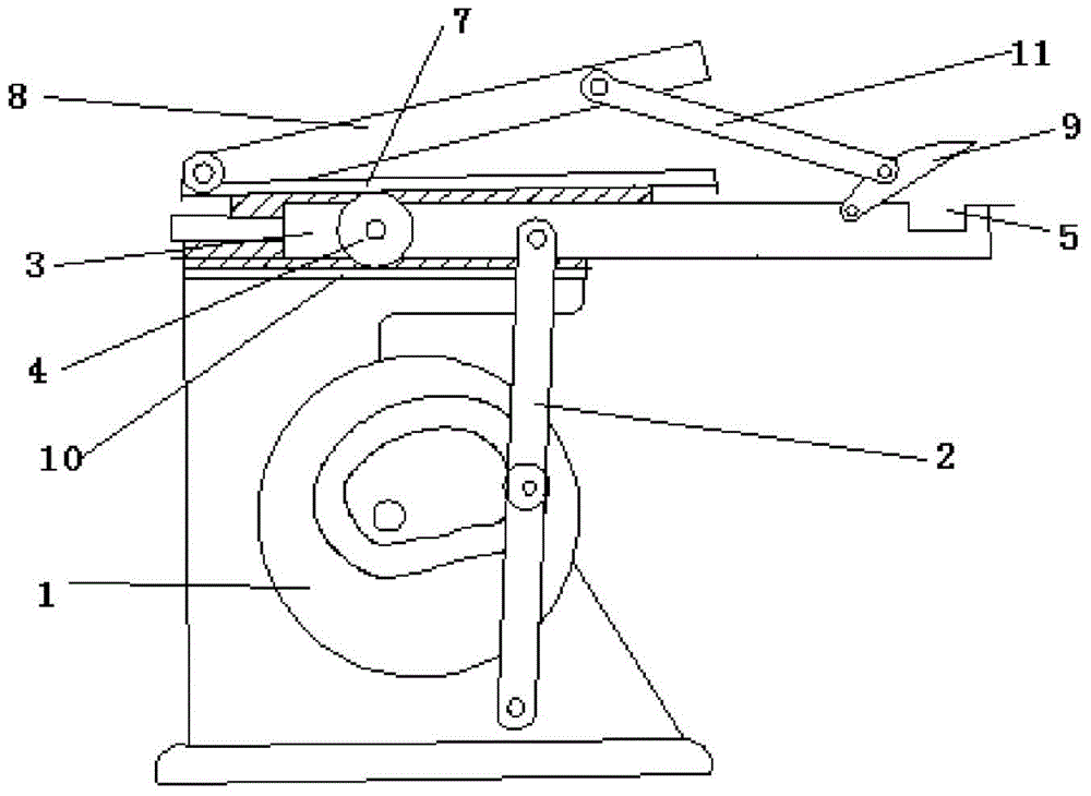
[0012] The reference signs in the description of the drawings are: cam mechanism 1, swing push rod 2, clamping device 3, transmission gear 4, clamping part 5, pressing plate 6, sliding plate 7, transmission pull rod 8, pressing plate 9 , the first rack 10, the linkage arm 11.

[0013] Such as figure 1 As shown, the technical solution provides a clamping and conveying device for workpieces, including a frame, a control device and a conveying device. The conveying device includes a cam mechanism 1 , a swing push rod 2 , and a clamping device 3 . In order to make the device compact in structure, preferably, the cam mechanism 1 is a grooved cam mechanism 1, which makes the swing push rod 2 swing on its end surface, thereby saving swing space. The middle part of the swing push rod 2 is connected to the rolling element of the cam mechanism 1, and the two ends of the swing push rod 2 are respectively on the frame and the clamping device 3, and the two sides of the clamping device 3 ...


PUM


Abstract

The invention relates to a workpiece clamping and conveying device which comprises a machine frame, a control device and a conveying device. The conveying device comprises a cam mechanism, a swing push rod and a clamping device. The middle of the swing push rod is connected to the cam mechanism. The two ends of the swing push rod are arranged on the machine frame and the clamping device respectively. The clamping device is horizontally connected to the machine frame in a sliding mode. A transmission gear is rotationally connected to the side wall of the clamping device. The machine frame is further fixedly provided with a first rack. One end of the clamping device is provided with a clamping portion capable of containing a workpiece. A compressing plate is hinged to the clamping portion. The control device comprises a sliding plate. The sliding plate is connected to the machine frame in a sliding mode. The sliding plate is fixedly provided with a second rack. The second rack is meshed with the transmission gear. A transmission pull rod is hinged to the sliding plate. A linkage arm is hinged to the other end of the transmission pull rod and hinged to the compressing plate. By means of the workpiece clamping and conveying device, the problem that conveying is unstable or the equipment cost is high in the existing workpiece conveying process is solved.

Description

technical field [0001] The invention relates to workpiece conveying equipment, in particular to a clamping conveying device for workpieces. Background technique [0002] In workpiece production, processing and manufacturing, workpieces need to be transferred between every two processing stations. At present, CNC equipment or transmission belts are generally used to transfer workpieces. As for the CNC sorting method, since such equipment often needs to be debugged and the price is high, it is usually not suitable for small processing plants. For the way of conveyor belt, there are many uncertain factors in the transmission of workpieces in the conveyor belt, especially for circular workpieces. During the transmission process, if the workpieces are not well positioned, the workpieces will roll around and collisions will occur between workpieces. , mutual friction, etc., which may cause greater wear on the workpiece, thereby affecting the quality of the workpiece. Contents o...

Claims


Application Information

Patent Timeline
IPC IPC(8): B65G25/04
Inventor 张水泉
Owner CHONGQING QUANHAI MACHINERY
Why Eureka
Try Eureka