Pipe conveying device

A technology for feeding pipes and material pipes, applied in the field of pipe feeding devices, can solve the problems of high labor intensity of operators and can not meet industrial requirements, etc., and achieve the effects of reducing labor intensity, reducing occupied space, and improving work efficiency

Active Publication Date: 2015-04-22
PROSYST ELECTRONICS TECH
View PDF5 Cites 3 Cited by
  • Summary
  • Abstract
  • Description
  • Claims
  • Application Information

AI Technical Summary

Problems solved by technology

In the process of product production, it is often necessary for the operator to take out the material tube from the material tube storage rack, and then send the material tube into the material tube collection tank, but due to manual operation, the labor intensity of the operator is often relatively high. Large, far from meeting industrial requirements

Method used


Image

  • Pipe conveying device
  • Pipe conveying device
  • Pipe conveying device

Examples


Embodiment Construction

[0025] In the following, the present invention will be further described in conjunction with the accompanying drawings and specific embodiments, so as to understand the technical ideas claimed in the present invention more clearly.

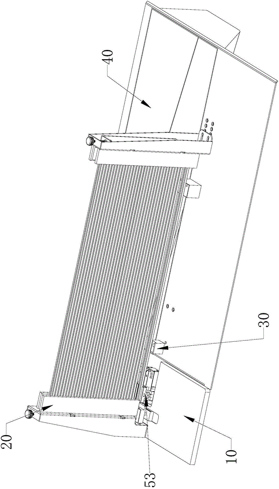
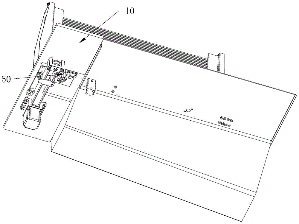
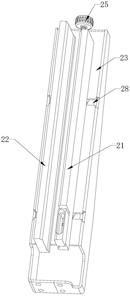
[0026] Such as Figure 1-7 As shown, it is the pipe delivery device of the present invention, which includes a main support base 10, a material tube storage assembly installed on the main support base 10, a transfer assembly 50, and a material tube collection tank 40 located in front of the material tube storage assembly; The tube storage assembly includes a bracket 20 and a pipe jacking mechanism 30; the bracket 20 includes a front tube plate 21 and a rear tube plate 22; a discharge area is provided below the front tube plate 21; the tube jacking mechanism 30 It includes a lifting base 31 for lifting the material tube 70 between the front baffle tube plate 21 and the rear baffle tube plate 22 and driving the material tube 70 up and down, and driv...


PUM


Abstract

The invention discloses a pipe conveying device which comprises a main supporting base, a pipe storage assembly, a transferring assembly and a pipe collecting tank, wherein the pipe storage assembly and the transferring assembly are arranged on the main supporting base, and the pipe collecting tank is located in front of the pipe storage assembly. The pipe storage assembly comprises a support and a pipe ejecting mechanism. The support comprises a front pipe baffle and a rear pipe baffle, and a discharging area is arranged below the front pipe baffle. The pipe ejecting mechanism comprises a lifting base and a lifting drive device, wherein the lifting base is used for ejecting and supporting pipes between the front pipe baffle and the rear pipe baffle and driving the pipes to ascend and descend, and the lifting drive device is used for driving the lifting base to move up and down in the height direction of the support. The transferring assembly comprises a clamping assembly and a first drive device, wherein the first drive device is used for driving the clamping assembly to transfer the pipes between the pipe storage assembly and the pipe collecting tank. The pipe conveying device can reduce labor intensity of operators, the length of the device can be reduced, and occupied space is reduced.

Description

technical field [0001] The invention relates to a pipe feeding device. Background technique [0002] As a packaging tube, the material tube is often used to package IC, integrated circuit, integrated block, semiconductor, electronic components and other components to prevent damage to the components during transportation. In the process of product production, it is often necessary for the operator to take out the material tube from the material tube storage rack, and then send the material tube into the material tube collection tank, but due to manual operation, the labor intensity of the operator is often relatively high. Large, far from meeting industrial requirements. Contents of the invention [0003] In order to overcome the deficiencies of the prior art, the object of the present invention is to provide a tube delivery device, which can take out the material tube from the material tube storage assembly and send it into the material tube collection tank, thereby redu...

Claims


Application Information

Patent Timeline
Patent Type & Authority Applications(China)
IPC IPC(8): B65G59/06
Inventor 周秋香
Owner PROSYST ELECTRONICS TECH
Why Eureka
Try Eureka