Conveying device used for machining chase mortises of wood floor

A technology of groove and tenon processing and conveying device, which is applied in the field of wood processing, can solve the problems of low efficiency, imperfection and low precision of groove and tenon processing of wooden floors, and achieves the effect of improving the controllability and wide application of equipment.

Inactive Publication Date: 2015-04-22
HUZHOU NANXUN SHUANGLIN ZHENSEN WOOD PROCESSING FACTORY
View PDF7 Cites 4 Cited by
  • Summary
  • Abstract
  • Description
  • Claims
  • Application Information

AI Technical Summary

Problems solved by technology

At present, the processing and molding process of wooden flooring is not perfect, and still requires a lot of manual assistance, the processing efficiency is low, the accuracy is poor, multiple calibrations are required, and the cost is relatively high, especially for wooden floor grooves and tenons. There are still many aspects that need to be improved in the design of processing conveying equipment
[0003] The existing conveying device for wood floor groove and tenon processing can usually only transport one specification of wood floor to the subsequent groove and tenon processing equipment for processing, or a large number of adjustments are required to process other specifications of wood floor, which is There is a problem of single processed product and multiple calibrations, which leads to the problems of low efficiency, low precision, poor controllability and high cost of wood floor groove and tenon processing

Method used


Image

  • Conveying device used for machining chase mortises of wood floor
  • Conveying device used for machining chase mortises of wood floor

Examples


Embodiment 1

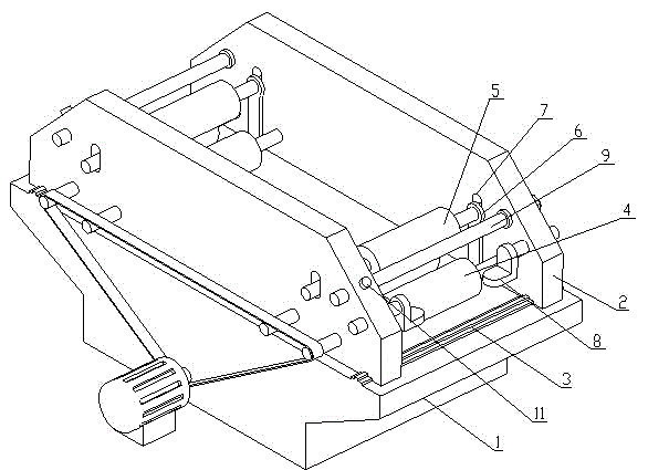
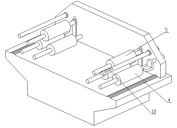
[0016] Embodiment 1 of the present invention: a conveying device for wood floor groove and tenon processing, such as figure 1 and figure 2 As shown, it includes a base 1, a body 2, a slide rail 3, a conveying roller 4, a pressure roller 5, a lifting plate 6 and a limit hole 7, the body 2 is arranged on the base 1, the slide rail 3 is arranged on the base 1, and the body 2 Adapted to the slide rail 3, the body 2 can slide on the slide rail 3, the conveying roller 4 is set at the lower part of the body 2, the lifting plate 6 is set on the base 1, and the driving device on the base 1 can make the lifting plate 6 go up and down, press The roller 5 is arranged on the lifting plate 6, the pressure roller 5 rises and falls together with the lifting plate 6, the limit hole 7 is arranged on the body 2, the limit hole 7 is adapted to the pressure roller 5, and the limit hole 7 limits the pressure roller 5 only Move vertically.

[0017] In particular, a guide block 8 is provided on th...

Embodiment 2

[0020] Embodiment 2 of the present invention: a conveying device for wood floor groove and tenon processing, including a base 1, a body 2, a slide rail 3, a conveying roller 4, a pressure roller 5, a lifting plate 6 and a limit hole 7, and the body 2 Set on the base 1, the slide rail 3 is set on the base 1, the body 2 is adapted to the slide rail 3, the body 2 can slide on the slide rail 3, the conveying roller 4 is set on the lower part of the body 2, and the lifting plate 6 is set on the base 1 Above, the driving device on the base 1 can lift the lifting plate 6 up and down, the pressure roller 5 is arranged on the lifting plate 6, the pressure roller 5 rises and falls together with the lifting plate 6, the limit hole 7 is arranged on the body 2, the limit hole 7 Adapted to the pressure roller 5, the limiting hole 7 restricts the pressure roller 5 to move only in the vertical direction.

[0021] In particular, a guide block 8 is provided on the machine body 2, and the guide ...

Embodiment 3

[0022] Embodiment 3 of the present invention: a conveying device for wood floor groove and tenon processing, including a base 1, a body 2, a slide rail 3, a conveying roller 4, a pressure roller 5, a lifting plate 6 and a limit hole 7, and the body 2 Set on the base 1, the slide rail 3 is set on the base 1, the body 2 is adapted to the slide rail 3, the body 2 can slide on the slide rail 3, the conveying roller 4 is set on the lower part of the body 2, and the lifting plate 6 is set on the base 1 Above, the driving device on the base 1 can lift the lifting plate 6 up and down, the pressure roller 5 is arranged on the lifting plate 6, the pressure roller 5 rises and falls together with the lifting plate 6, the limit hole 7 is arranged on the body 2, the limit hole 7 Adapted to the pressure roller 5, the limiting hole 7 restricts the pressure roller 5 to move only in the vertical direction.

[0023] The use method of the present invention: the wooden floor is sent to the conveyi...


PUM


Abstract

The invention discloses a conveying device used for machining chase mortises of a wood floor. The conveying device comprises a base (1), device bodies (2), sliding rails (3), conveying rolls (4), pressing rolls (5), lifting plates (6) and limiting holes (7). The device bodies (2) are arranged on the base (1), the sliding rails (3) are arranged on the base (1), the device bodies (2) are matched with the sliding rails (3), the conveying rolls (4) are arranged on the lower portions of the device bodies (2), the lifting plates (6) are arranged on the base (1), the pressing rolls (5) are arranged on the lifting plates (6), and the limiting holes (7) are formed in the device bodies (2) and matched with the pressing rolls (5). Wood floors of different widths and thicknesses can be conveyed to follow-up chase mortise machining equipment through the conveying device, and the conveying device has the advantages of being high in adaptability, precision and efficiency and low in cost.

Description

technical field [0001] The invention relates to a solid wood processing device, in particular to a conveying device for wood floor groove and tenon processing, which belongs to the field of wood processing. Background technique [0002] Wood flooring is healthy and environmentally friendly, and has always been favored by people, especially in home decoration. At present, the processing and molding process of wooden flooring is not perfect, and still requires a lot of manual assistance, the processing efficiency is low, the accuracy is poor, multiple calibrations are required, and the cost is relatively high, especially for wooden floor grooves and tenons. There are still many aspects of the processing conveying equipment that need to be designed and improved. [0003] The existing conveying device for wood floor groove and tenon processing can usually only transport one specification of wood floor to the subsequent groove and tenon processing equipment for processing, or a ...

Claims


Application Information

Patent Timeline
Patent Type & Authority Applications(China)
IPC IPC(8): B65H20/02
CPCB65H20/02
Inventor 俞金根柴凌燕
Owner HUZHOU NANXUN SHUANGLIN ZHENSEN WOOD PROCESSING FACTORY
Why Eureka
Try Eureka