Pressure stabilizing valve of adjustable pressure type turbocharger

A technology of turbocharger and pressure stabilizing valve, which is applied in the direction of machines/engines, internal combustion piston engines, mechanical equipment, etc., and can solve problems such as the adjustment of the maximum intake pressure value of engines that cannot be boosted

Inactive Publication Date: 2015-04-22
孙万军
View PDF7 Cites 4 Cited by
  • Summary
  • Abstract
  • Description
  • Claims
  • Application Information

AI Technical Summary

Problems solved by technology

[0003] In view of this, in order to solve the problem that the traditional supercharger regulator valve cannot adjust the maximum intake pressure value of the supercharged engine, the present invention provides a device that can adjust the maximum intake pressure value of the supercharged engine at any time after installation. Booster regulator valve

Method used


Image

  • Pressure stabilizing valve of adjustable pressure type turbocharger

Examples


Embodiment 1

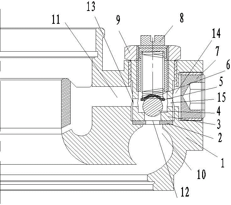
[0021] refer to figure 1 , a pressure-adjustable turbocharger regulator valve, which is installed on the casing of the compressor volute 1 of the turbocharger. The first pressure relief passage 10 communicates with the second pressure relief passage 11 connected to the air inlet of the compressor. The first pressure relief channel 10 and the second pressure relief channel 11 are integrated into a cylindrical depression at the edge of the compressor volute 1; the pressure stabilizing valve includes a pressure stabilizing valve housing 3, and the stabilizing The pressure valve housing 3 is a hollow cylinder with threads on the inner and outer surfaces, and is screwed into the cylindrical recess by the threads on the inner surface of the cylindrical recess at the edge of the compressor volute 1 . The center of the bottom end of the pressure stabilizing valve housing 3 is provided with a circular opening 12, and there is a sealing ring 2 between the bottom end of the pressure sta...

Embodiment 2

[0024] The difference between embodiment 2 and embodiment 1 is that the central axis of the pressure stabilizing valve housing 3 and the central axis of the compressor volute 1 in embodiment 2 are placed on the edge of the compressor volute perpendicular to each other.

[0025] Beneficial effects of the present invention:

[0026] A: The spring cushion 5 protects the steel ball 4 from the friction wear of the pneumatic spring 6 to maintain the sealing accuracy of the steel ball 4; the pressure stabilizing valve housing 3 can protect the compressor volute 1 from the pressure regulating valve plug 8 Frictional damage from frequent turning during adjustment.

[0027] B: The downward pressure on the floating valve 4 depends on the pressure of the pneumatic spring 6, and the pressure of the pneumatic spring 6 depends on the distance that the pressure regulating valve plug 8 is screwed into the pressure stabilizing valve housing 3, so it can be adjusted according to the specific wo...


PUM


Abstract

The invention provides a pressure stabilizing valve for an adjustable pressure type turbocharger. The pressure stabilizing is mounted on a housing of a compressor volute of the turbocharger; the compressor volute is equipped with a first pressure release channel which communicates with high pressure air in the turbocharger, and a second pressure release channel which communicates with an air inlet of the compressor volute. The pressure stabilizing valve of the adjustable pressure type turbocharger is characterized in that the first pressure release channel and the second pressure release channel are combined into a cylindrical sunken part in the side edge of the compressor volute; the pressure stabilizing valve comprises a housing which is a hollow circular barrel of which both the inner surface and the outer surface are equipped with threads; the threads in the inner surface of the cylindrical sunken part in the side edge of the compressor volute are screwed into the cylindrical sunken part; an opening which communicates with the first pressure release channel is formed in the bottom end of the housing; a plurality of ventilating holes are formed in the side surface of the housing; the first through hole communicates with the second pressure release channel.

Description

technical field [0001] The patent of the invention relates to a pressure-adjustable turbocharger regulator valve, which is suitable for exhaust gas turbochargers of various diesel engines, can adjust the maximum output air pressure of the compressor volute, and output the maximum pressure of compressed air stably , to prevent the supercharger output pressure from being too high, causing the engine explosion pressure to be too high, and protecting the engine. Background technique [0002] With the development of technology, exhaust gas turbocharger is more and more applied to various engines because of its ability to increase engine power per liter, reduce exhaust emissions, save energy and reduce consumption. When the turbocharger is working, as the speed and power of the engine increase, the outlet pressure provided by the turbocharger is also increasing. When the intake pressure exceeds the allowable pressure ratio of the engine, the compressor volute is installed The r...

Claims


Application Information

Patent Timeline
Patent Type & Authority Applications(China)
IPC IPC(8): F02B37/16
CPCY02T10/12
Inventor 孙万军
Owner 孙万军
Why Eureka
Try Eureka