Connecting structure of combined type valve

A connection structure, combined technology, applied in the field of hydraulic valves, can solve the problems of loosening, reducing sealing and reliability, etc.

Pending Publication Date: 2019-05-17
DING SI SHANGHAI HYDRAULIC TECH CO LTD
View PDF0 Cites 0 Cited by
  • Summary
  • Abstract
  • Description
  • Claims
  • Application Information

AI Technical Summary

Problems solved by technology

[0003] In view of the disadvantages that the fasteners of the connecting structure of the existing combined valve are easy to loose due to dynamic fatigue and reduce the sealing and reliability, the applicant provides a connecting structure

Method used


Image

  • Connecting structure of combined type valve
  • Connecting structure of combined type valve
  • Connecting structure of combined type valve

Examples


Embodiment 1

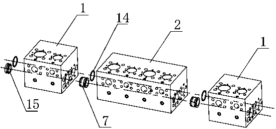
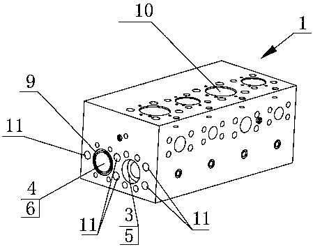
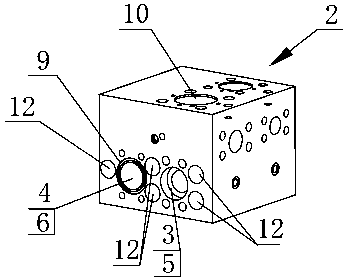
[0026] Such as figure 1 , figure 2 As shown, the basic valve block 1 is provided with an oil inlet pipe 3 and an oil return pipe 4 inside. The oil inlet pipe 3 and the oil return pipe 4 run through the body of the valve block, and an oil inlet pipe port 5 and an oil return pipe port 6 are formed on both ends of the valve block. The oil inlet pipe ports 5 on both sides are provided with step holes, the oil return pipe port 6 on one side of the basic valve block 1 is provided with a gasket groove 9, and the other side end surface is not provided with a gasket groove 9. The sealing ring 14 is arranged in the gasket groove 9 and is used for sealing the joint of the oil return pipe 6 . Several valve holes 10 are provided inside the basic valve block 1 for forming oil passages or installing cartridge valves. The cartridge valve is connected with the oil inlet pipe 3, the oil return pipe 4 and each pipeline forming the oil circuit, and controls each oil circuit to be connected or ...

Embodiment 2

[0033] In this embodiment, no thread is provided on the basic valve block 1, but a through hole is provided at this position. The threaded rods at both ends are used to pass through the through holes of the entire basic valve block 1 and the extended valve block 2, and nuts are used to lock the two ends of the rods, which can also meet the fastening requirements. Of course, long bolts can also be used, and the other end is locked with a nut.

Embodiment 3

[0035] Such as Figure 7 and Figure 8 As shown, the combined valve in Embodiment 1 is also provided with a transition block 16 that realizes the combined connection of the large-size valve block and the small-size valve block. The expansion valve block 2 is connected by a transition block 16. The transition block 16 is connected to the position and diameter of the oil inlet pipe 5 and the oil return pipe 6 at one end of the large-size valve block and the oil inlet pipe 5 of the large-size valve block. It is equivalent to the oil return pipe port 6; the other end is equivalent to the oil inlet pipe port 5 and the oil return pipe port 6 of the small size valve block, the two-way sealing joint 7 placed at the oil inlet pipe port 5, and the gasket groove 9 arranged at the oil return pipe port 6 , The sealing ring 14 is the same as the above embodiment. The inside of the transition block 16 realizes diameter reduction through stepped holes, tapered holes, staggered holes, etc., ...


PUM


Abstract

The invention discloses a connecting structure of a combined type valve. At least two valve blocks are combined and used, the two adjacent valve blocks are butted at the end surfaces through a fastening structure, and the number of fixing holes around high-pressure pipe orifices is more than the number of fixing holes around low-pressure pipe orifices. According to the connecting structure of thecombined type valve, more fixing holes are arranged on the periphery of high-pressure oil inlet pipe orifices so that the tightness of oil inlet pipes can be effectively ensured, and less fixing holesare arranged on the periphery of low-pressure oil return pipe orifices so that the sealing requirement of the low-pressure pipe orifices can also be met. According to the connecting structure of thecombined type valve, fasteners are directly arranged on the periphery of the oil inlet pipe orifices or the oil return pipe orifices, instead of being simply arranged at four corners of each valve block, so that internal space of the valve blocks is reasonably utilized, and meanwhile, the locking force can be provided for pipe orifice sealing devices, so that dynamic fatigue loosening of the fasteners caused by frequent changes in charging and discharging liquid pressure is avoided, and the sealing effect and reliability of the device are effectively improved.

Description

technical field [0001] The invention relates to the technical field of hydraulic valves, in particular to a connection structure of combined valves. Background technique [0002] Combined valves are widely used in hydraulic control fields of various construction machinery, industrial machinery and agricultural machinery. As the number of hydraulic equipment needs to be controlled increases, the use of combined valves can reduce the difficulty of manufacturing a single valve, thereby forming standardized production, reducing the cost of manufacturing and inventory preparation, and has better scalability, suitable for new equipment R & D or upgrade and improvement of mature products. The connection structure of the existing valve block system is mostly to simply set the fasteners at the four corners of the valve block. The frequent changes in the filling and discharging pressure of the hydraulic system will cause dynamic fatigue and loosening of the fasteners, thus making the...

Claims


Application Information

Patent Timeline
IPC IPC(8): F15B13/02
Inventor 杨棋君
Owner DING SI SHANGHAI HYDRAULIC TECH CO LTD
Why Eureka
Try Eureka