Transfer case

A transfer case and case technology, which is applied in the field of transfer case, can solve problems such as poor coordination between bearings and bearing holes, and achieve the effect of prolonging the service life and broadening the application range

Inactive Publication Date: 2015-04-22
CRRC BEIJING ERQI LOCOMOTIVE CO LTD
View PDF7 Cites 0 Cited by
  • Summary
  • Abstract
  • Description
  • Claims
  • Application Information

AI Technical Summary

Problems solved by technology

[0004] The invention provides a transfer case, which can solve the problem of poor coordination between the bearing and the bearing hole in the existing transfer case, so as to prolong the service life of the transfer case

Method used


Image

  • Transfer case
  • Transfer case
  • Transfer case

Examples


Embodiment Construction

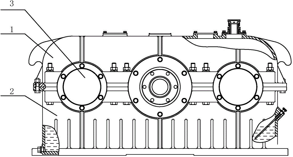
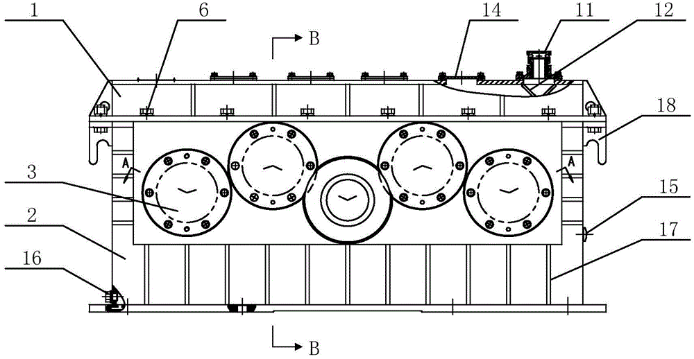
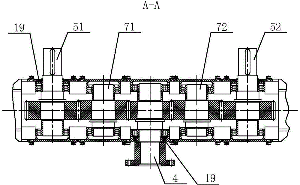
[0027] figure 2 The front view of the transfer case provided by the embodiment of the present invention, image 3 A top view of the transfer case A-A direction provided for the embodiment of the present invention, Figure 4 The left view of the transfer case B-B direction provided for the embodiment of the present invention. like Figure 2 to Figure 4 As shown, the embodiment of the present invention provides a transfer case, comprising: an upper case body 1 formed by welding and a lower case body 2 formed by welding, and the upper case body 1 and the lower case body 2 are screwed together. At least two pairs of bearing holes 3 are provided on the lower box body 2, which are respectively used for passing through the input shaft and the output shaft.

[0028] Wherein, the lower box body 2 is used to accommodate the input shaft and the output shaft, the input shaft and the output shaft are meshed by gears, the input shaft is connected to the power supply equipment, such as a...


PUM


Abstract

The invention provides a transfer case. The transfer case comprises an upper case body formed by welding and a lower case body formed by welding. The upper case body is in threaded connection with the lower case body, and at least two pairs of bearing holes are formed in the lower case body and used for an input shaft and an output shaft to penetrate in. By means of the transfer case, the problem of poor matching between a bearing and the bearing holes of an existing transfer case is solved, and therefore, the service life of the transfer case is prolonged.

Description

technical field [0001] The invention relates to mechanical transmission equipment technology, in particular to a transfer case. Background technique [0002] The transfer case is a device that can redistribute the power output by the engine to drive other equipment. For example, in the field of construction machinery, the power output by the diesel engine can also drive hydraulic pumps, generators, etc. after the speed is adjusted by the transfer case to drive the construction machinery equipment to drive and operate. [0003] At present, the transfer case body is mostly made of casting technology. figure 1 It is a structural schematic diagram of a transfer case in the prior art, such as figure 1 As shown, the transfer case includes two parts, the upper case body 1 and the lower case body 2, which are respectively cast. The upper case body 1 and the lower case body 2 are respectively provided with semicircular gaps, and the upper case body 1 and the lower case body 2 pass ...

Claims


Application Information

Patent Timeline
IPC IPC(8): F16H57/02F16H57/021
CPCF16H57/02F16H57/021
Inventor 林文光钱兆勇全君马泳
Owner CRRC BEIJING ERQI LOCOMOTIVE CO LTD
Why Eureka
Try Eureka