A two-stage solar heat absorber

A technology for solar heat absorbers and heat absorbing areas, which is applied in the field of solar energy applications, can solve the problems of poor practicability of heat absorbers, insufficient consideration of Gaussian distribution characteristics of concentrated solar energy flow density, etc., and achieve good heat resistance and high reliability Effect

Inactive Publication Date: 2016-09-28
FUJIAN UNIV OF TECH
View PDF12 Cites 0 Cited by
  • Summary
  • Abstract
  • Description
  • Claims
  • Application Information

AI Technical Summary

Problems solved by technology

The current structural design of solar heat absorbers focuses on the enhanced heat transfer of the working medium (referred to as working fluid) inside the heat absorber, and the Gaussian distribution characteristics of the concentrated solar energy flow density are not considered deeply enough, resulting in poor practicability of the heat absorber

Method used


Image

  • A two-stage solar heat absorber
  • A two-stage solar heat absorber

Examples


Embodiment 1

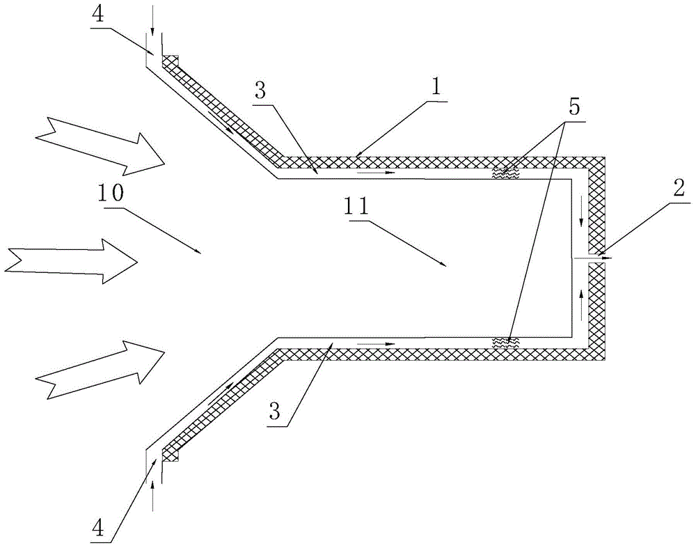
[0047] refer to figure 1 , the present invention provides a two-stage heat-absorbing solar heat absorber, comprising a cavity 1, the cavity is divided into a low-temperature heat-absorbing zone 10 and a high-temperature heat-absorbing zone 11, the high-temperature heat-absorbing zone 11 is a cylindrical shape with one end open, and the cavity The bottom end of the body 1 is provided with a working medium outlet 2; the low-temperature heat absorption area 10 is a truncated conical structure; the inner wall of the cavity 1 is provided with an interlayer channel 3 for accommodating the passage of the air working medium, and the interlayer channel 3 is located at the edge of the truncated conical structure. There is an air working medium inlet 4, and the interlayer channel 3 is located in a section of the high-temperature heat-absorbing area. A foam material 5 is arranged in a section of the channel to strengthen the heat exchange between the working medium and the high-temperature...

Embodiment 2

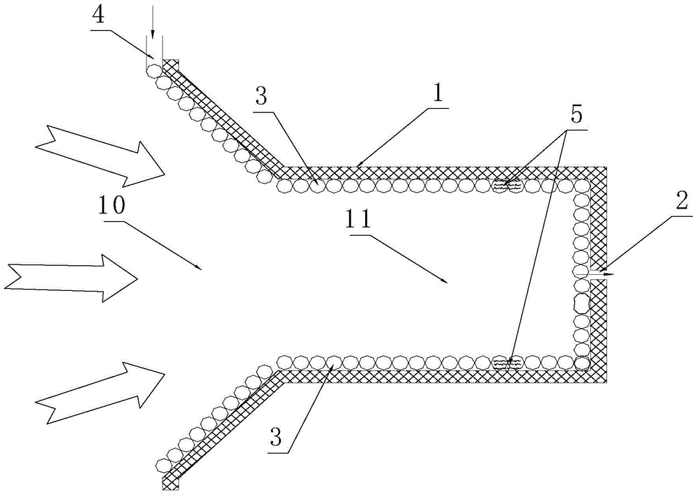
[0050] refer to figure 2 , the present invention provides a two-stage heat-absorbing solar heat absorber, comprising a cavity 1, the cavity is divided into a low-temperature heat-absorbing zone 10 and a high-temperature heat-absorbing zone 11, the high-temperature heat-absorbing zone 11 is a cylindrical shape with one end open, and the cavity The bottom end of the body 1 is provided with a working fluid outlet 2; the low-temperature heat absorption area 10 is a truncated conical structure; the inner wall of the cavity 1 is provided with an interlayer channel 3 for accommodating the passage of the air working medium, and the interlayer channel 3 is located at the edge of the truncated conical structure. There is an air working medium inlet 4, and the interlayer channel 3 is located in a section of the high-temperature heat-absorbing area. A foam material 5 is arranged in a section of the channel to strengthen the heat exchange between the working medium and the high-temperature...


PUM


Abstract

The invention discloses a two-stage heat-absorbing solar heat absorber, which comprises a cavity, the cavity is divided into a low-temperature heat-absorbing area and a high-temperature heat-absorbing area, the high-temperature heat-absorbing area is cylindrical with one end open, and the bottom of the cavity is There is a working medium outlet; the low-temperature heat absorption area is a truncated conical structure; the inner wall of the cavity is provided with an interlayer channel for the air working medium to pass through, and the interlayer channel is located at the edge of the truncated conical structure. The gas entrance enters the interlayer channel where the working fluid flows, passes through the low-temperature heat absorption area, and the low-density solar flow at the edge of the absorption spot is preheated to heat up, and then enters the high-temperature heat absorption area, where the high-density solar flow in the center of the absorption spot reaches a high temperature state, and finally passes through the working fluid The outlet flows out of the heat absorber to complete the light-to-heat conversion. The invention fully considers the Gaussian distribution characteristics of the spot solar flux density, and divides the heat absorber into a low-temperature heat absorption area and a high-temperature heat absorption area, which is beneficial to reducing the radiation heat dissipation loss of the heat absorber and improving the thermal efficiency of the heat absorber.

Description

technical field [0001] The invention relates to the technical field of solar energy applications, in particular, the invention relates to a two-stage solar heat absorber. Background technique [0002] Solar energy is an abundant and clean energy source. The development and utilization of solar energy resources is very important for energy conservation, emission reduction and improvement of ecological environment. The solar heat absorber converts concentrated sunlight into a high-temperature heat source, heats the working medium to do work or drives a chemical reaction, and is the core device of the solar high-temperature heat conversion system. According to different functions that can be realized, there are many solar heat absorber schemes that have been proposed at present. [0003] On the website of the State Intellectual Property Office of the People's Republic of China, 7 patents related to the present invention were found, and the specific information is as follows: ...

Claims


Application Information

Patent Timeline
Patent Type & Authority Patents(China)
IPC IPC(8): F24J2/04F24J2/46F24J2/24F24S10/70
CPCY02E10/44
Inventor 戴贵龙杜晓瑞侯根富
Owner FUJIAN UNIV OF TECH
Why Eureka
Try Eureka