
Groove type solar heat collecting tube for high temperature

A trough solar energy and heat collecting tube technology is applied in the direction of solar heat collectors, solar heat collectors, and solar thermal energy using working fluid, which can solve the problems of increasing operating costs, increasing heat loss, and increasing operating heat loss, etc. Achieve the effect of reducing system operation heat loss, radiation heat transfer loss, and improving effective utilization.

Pending Publication Date: 2018-08-03
INST OF ELECTRICAL ENG CHINESE ACAD OF SCI
View PDF0 Cites 0 Cited by
  • Summary
  • Abstract
  • Description
  • Claims
  • Application Information

AI Technical Summary

Problems solved by technology

However, due to the radiative heat loss of the trough-type solar collector tube increasing with the temperature of the heat transfer working medium, the relationship of the fourth power increases, resulting in a sharp increase in heat loss with the increase of the working medium temperature, especially the solidification temperature of the molten salt working medium Above 200°C, in order to prevent the solidification of the molten salt working medium, the system needs to be maintained at high temperature at night, resulting in a significant increase in operating heat loss and increased operating costs
Although the power generation efficiency of the steam turbine increases due to the increase of the steam temperature, the thermal efficiency of the trough solar thermal collection system decreases due to the increase of heat loss, resulting in a trough solar thermal power generation technology with higher temperature molten salt or water / steam as the heat transfer medium develop slowly
At the same time, the trough solar thermal power generation technology using molten salt or water / steam as the heat transfer medium requires a higher concentration ratio, and the concentrator opening width is larger, resulting in part of the concentration spot exceeding the diameter of the metal inner tube width, wasting part of the sun's concentrated radiant energy

Method used


Image

  • Groove type solar heat collecting tube for high temperature
  • Groove type solar heat collecting tube for high temperature
  • Groove type solar heat collecting tube for high temperature

Examples


Embodiment Construction

[0023] Embodiments of the present invention will be described in detail below in conjunction with the accompanying drawings.

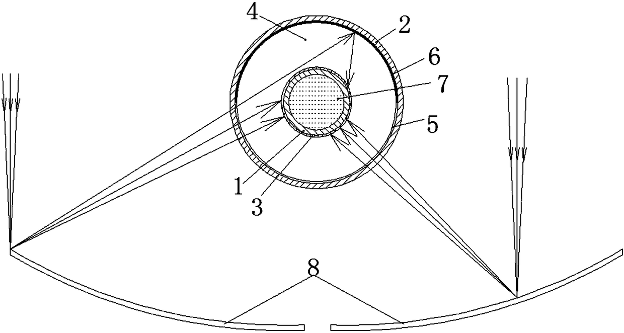
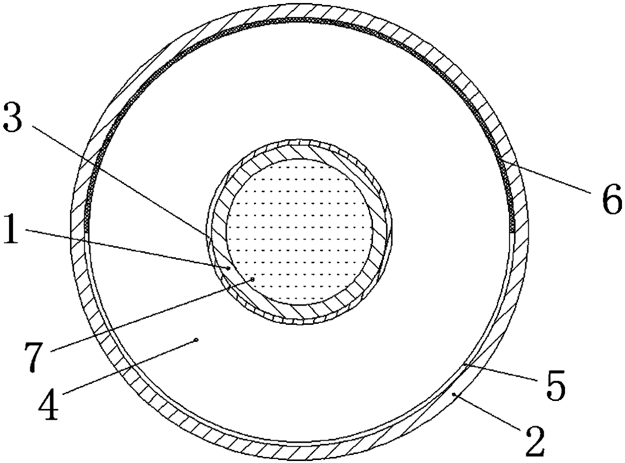
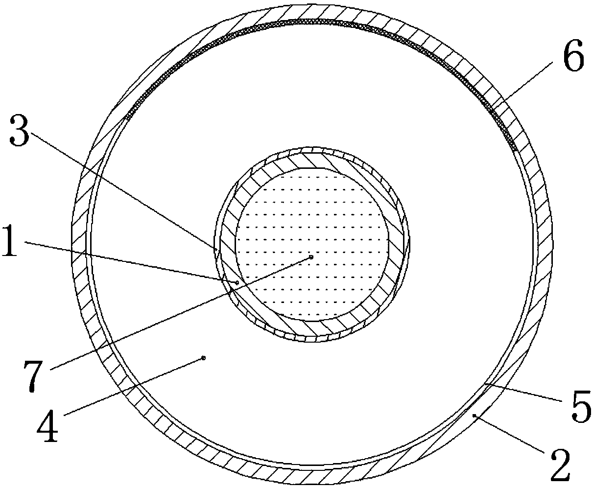
[0024] Embodiment 1 of the present invention is used for the trough type solar collector tube of high temperature as figure 1 and figure 2 As shown, it includes a glass outer tube 2 and a metal inner tube 1, the metal inner tube 1 has a high temperature resistant selective absorption coating 3, the glass outer tube 2 is coaxially sleeved outside the metal inner tube 1, and the glass outer tube 2 and the metal An annular vacuum closed space 4 is formed between the inner tubes 1 . The heat transfer working medium 7 in the metal inner tube 1 is high temperature molten salt. The selective absorbing coating 3 is made by magnetron sputtering equipment, and consists of four layers: an anti-reflective coating layer, a low-absorbing layer, a high-absorbing layer, and an infrared high-reflecting layer from outside to inside. The selective absorbing coating 3...


PUM


Abstract

The invention discloses a groove type solar heat collecting tube for high temperature. The heat collecting tube comprises a glass outer tube (2) and a metal inner tube (1), wherein the metal inner tube (1) is provided with a high-temperature-resistant selective absorbing coating (3), the glass outer tube (2) coaxially sleeves the metal inner tube (1), and an annular vacuum closed space (4) is formed between the glass outer tube (2) and the metal inner tube (1). The periphery of the inner wall of the glass outer glass tube (2) is divided into two parts of an illuminating surface (5) and a non-illuminating surface (6), the inner wall of the illuminating surface (5) of the glass outer tube (2) is provided with an antireflection film layer, and the antireflection film layer is located on a light-gathering side; and the inner wall of the non-illuminating surface (6) of the glass outer tube (2) is provided with a reflecting layer, and the reflecting layer is positioned on a non-light-gathering side, wherein the reflectivity of the reflecting layer is more than 85% of a silver film layer, a aluminum film layer or a copper film layer.

Description

technical field [0001] The invention relates to a trough solar heat collecting tube. Background technique [0002] Trough solar thermal power generation is currently the most widely used and low-cost solar thermal power generation technology in the world. It uses parabolic reflectors to reflect and focus sunlight to the lower part of the trough solar collector tube located on its focal line to heat the fluid in the tube. , and then generate high-temperature steam to drive the steam turbine to generate electricity. The trough solar collector tube is the most critical part of the conversion from light to heat in the trough solar thermal power generation system. It is generally composed of a metal inner tube and a coaxial glass outer tube. In order to reduce convective heat loss, the glass outer tube and the metal inner tube A closed annular vacuum space is formed between them, and the outer wall of the metal inner tube is coated with a selective absorption coating with high a...

Claims


Application Information

Patent Timeline
IPC IPC(8): F24S10/70F24S10/40F24S70/225F24S80/54F24S80/56
CPCY02E10/44
Inventor 雷东强任羽聪王志峰
Owner INST OF ELECTRICAL ENG CHINESE ACAD OF SCI
Learn More