Cathode structure for color cathode ray tube

Inactive Publication Date: 2004-07-22
MERIDIAN SOLAR & DISPLAY
View PDF5 Cites 1 Cited by
  • Summary
  • Abstract
  • Description
  • Claims
  • Application Information

AI Technical Summary

Benefits of technology

[0035] An advantage of the invention is to solve at least the above problems and / or disadvantages and to provide at least the advantages described hereinafter.
[0036] Accordingly, one advantage of the present invention is to solve the foregoing problems by providing a cathode structure with maximized thermal efficiency and minimized power consumption.
[0037] Another advantage of the present invention is to provide a cathode structure within a cathode ray tube capable of improving thermal efficiency by making a sleeve of the cathode transfer most of the radiant heat from the cathode's heater to its electron-emissive material layer, thereby reducing the radiant heat loss to outside, and by optimizing the length of a strap that fixes the sleeve and a holder, thereby minimizing conductive heat loss to the holder and power consumption of the heater.
[0038] The foregoing and other advantages are realized by providing a cathode structure for a cathode ray tube including: a sleeve with a built-in heater; a base metal covered with an electron-emissive material, the base metal being fixed to an upper end portion of the sleeve; and a holder for encompassing the sleeve, wherein the dimensions of the cathode structure satisfy the condition of -0.6 mm (H-(C+D)) 0.4 mm, in which H denotes a height of the cathode structure, C denotes a height of the base metal, and D denotes a length of the holder.
[0039] Another aspect of the invention presents a cathode structure for a cathode ray tube including: a sleeve with a built-in heater; a base metal covered with an electron-emissive material, the base metal being fixed to an upper end portion of the sleeve; and a holder for encompassing the sleeve, wherein a length from a lower end of the base metal to an upper end of the holder is in the range of about -0.6 to about 0.4 mm.
[0040] Another aspect of the invention presents a cathode structure for a cathode ray tube including: a sleeve with a built-in heater; a base metal covered with an electron-emissive material, the base metal being fixed to an upper end portion of the sleeve; and a holder for encompassing the sleeve, wherein a height of the cathode structure, H, a height of the base metal, C, and a length of the holder, D, satisfy a relation of H.ltoreq.C+D.

Problems solved by technology

Whether intended or not, the cathode is inevitably put in a high temperature environment, both during the manufacturing process and in the operation of the cathode.
The route of heat transfer, or heat transfer mechanism, is totally dependent on positions of each component of the cathode structure, and often gives rise to problems like deterioration of thermal efficiency and increase in power consumption that are be described below.
The above structural features lead to the following problems for the cathode structure embodying the same.
This structural limit consequently gives rise to a thermal efficiency problem through which heat is lost to the outside.
Another drawback or problem with the related art cathode structure is that the heat from the sleeve 43 is transferred by heat conduction not only to the base metal 42 but also to the strap 44.
However, there is a limit in the capacity of the related art cathode structure for reducing the amount of heat that is conducted to the strap 44.
When the thermal efficiency is lowered, the heater consumes more power.
As such, it gets more difficult to attain low power consumption.

Method used


Image

  • Cathode structure for color cathode ray tube
  • Cathode structure for color cathode ray tube
  • Cathode structure for color cathode ray tube

Examples


Embodiment Construction

[0053] Reference will now be made in detail to an embodiment of the present invention, example of which is illustrated in the accompanying drawings.

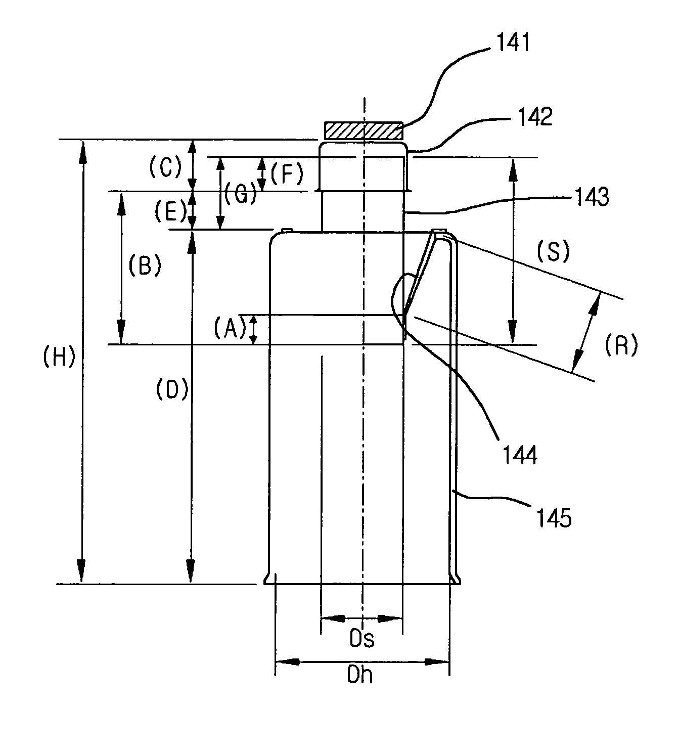
[0054] Referring first to FIG. 4, the cathode structure for a cathode ray tube according to the present invention is composed of an emitter 141, a base metal 142, a sleeve 143 with a built-in heater, a strap 144, and a holder 145.

[0055] The emitter 141, covered with an electron-emissive material layer, is applied to the base metal 142. The electron-emissive material has barium (Ba) as an active ingredient and further includes an alkaline-earth metal carbonate containing strontium (Sr) and calcium (Ca).

[0056] The sleeve 143 has a cylindrical shape and a built-in heater (not shown). The front end of the sleeve is inserted into the base metal 142. Hence, an upper end portion of the sleeve 143 is covered by the base metal 142. In addition, the sleeve 143 is fitted in the cylindrical-shaped holder 145 with a larger diameter than that of the s...


PUM


Abstract

The present invention relates to a cathode ray structure for a cathode ray tube, and more particularly, to a cathode structure for a cathode ray tube capable of maximizing thermal efficiency and minimizing power consumption.

Description

[0001] 1. Field of the Invention[0002] The present invention relates to a cathode ray structure for a cathode ray tube, and more particularly, to a cathode structure for a cathode ray tube capable of maximizing thermal efficiency and minimizing power consumption.[0003] 2. Background of the Related Art[0004] FIG. 1 is a diagram showing the structure of an already-known color cathode ray tube.[0005] In general, the color cathode ray tube is composed of the following: a front glass panel 3; a funnel 4 including a fluorescent screen 1 inside surface of the funnel 4, the fluorescent screen 1 being covered with R, G and B fluorescent substances or phosphors; a shadow mask 2 with a color selection function; and a tube-shaped neck portion 4a welded to a rear side of the funnel 4.[0006] Housed inside the neck portion 4a of the funnel 4 is an electron gun 5, and outside is a deflection yoke for deflecting electron beams emitted from the electron gun 5 in the horizontal and vertical directions...

Claims


Application Information

Patent Timeline
IPC IPC(8): H01J29/04H01J1/20
CPCH01J1/20H01J29/04
Inventor LEE, JAE SUN
Owner MERIDIAN SOLAR & DISPLAY
Why Eureka
Try Eureka