Extruded tube for use in heat exchanger

a technology of heat exchanger and extruder, which is applied in the direction of indirect heat exchangers, light and heating apparatus, other domestic objects, etc., can solve the problems of decreasing the thermal efficiency of the heat exchanger, and achieve the effects of maintaining the durability of the tube, maximizing the thermal efficiency of the heat exchanger, and minimizing the use of materials

Inactive Publication Date: 2009-04-02
VISTEON GLOBAL TECH INC
View PDF22 Cites 11 Cited by
  • Summary
  • Abstract
  • Description
  • Claims
  • Application Information

AI Technical Summary

Benefits of technology

[0006]Consistent and consonant with the present invention, an extruded tube for a heat exchanger, whereby a thermal efficiency of the heat exchanger is maximized, material usage is minimized, and a durability of the tube is maintained, has surprisingly been discovered.

Problems solved by technology

Prior art attempts to maximize the surface area of the tubes have had a negative affect on pressure drop within the tube, thus decreasing the thermal efficiency of the heat exchanger.

Method used


Image

  • Extruded tube for use in heat exchanger
  • Extruded tube for use in heat exchanger
  • Extruded tube for use in heat exchanger

Examples


Embodiment Construction

[0017]The following detailed description and appended drawings describe and illustrate various exemplary embodiments of the invention. The description and drawings serve to enable one skilled in the art to make and use the invention, and are not intended to limit the scope of the invention in any manner.

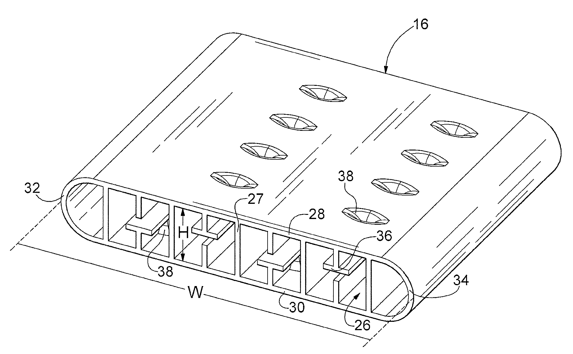
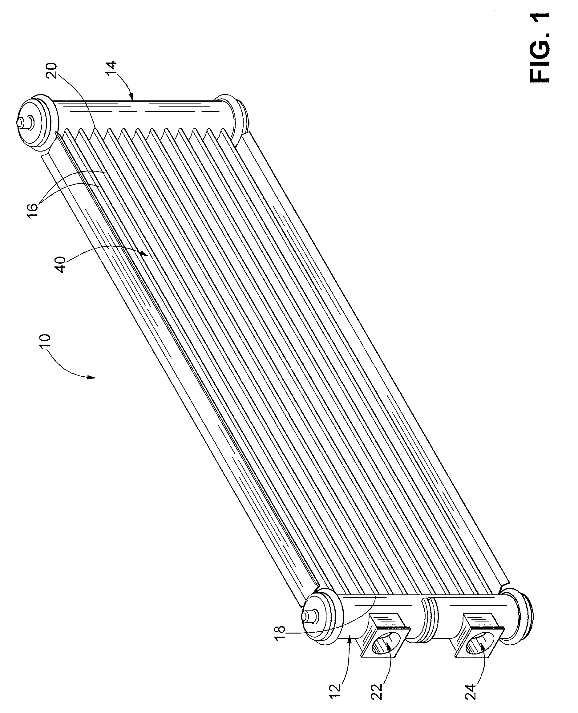
[0018]FIG. 1 shows a heat exchanger assembly 10 according to an embodiment of the invention. The heat exchanger assembly 10 includes a first manifold 12 and a second manifold 14 disposed on opposing ends thereof. In the embodiment shown, the heat exchanger assembly 10 is a U-flow type heat exchanger assembly. However, it is understood that other types of heat exchanger assemblies can be used such as a serpentine-flow type heat exchanger assembly, a parallel flow type heat exchanger assembly, and a multi-row parallel or counter-flow type heat exchanger assembly, for example. The heat exchanger assembly 10 also includes a plurality of substantially parallel tubes 16 disposed between an...


PUM

PropertyMeasurementUnit
temperatureaaaaaaaaaa
thermal efficiencyaaaaaaaaaa
surface areaaaaaaaaaaa

Abstract

An extruded tube for a heat exchanger is disclosed, the tube including a plurality of deformations formed therein, wherein the deformations of the extruded tube facilitates a maximization of a thermal efficiency of the heat exchanger.

Description

FIELD OF THE INVENTION[0001]The invention relates generally to an extruded tube for use in a heat exchanger, and more particularly to an extruded tube including a plurality of deformations formed on at least one surface thereof for use in a heat exchanger.BACKGROUND OF THE INVENTION[0002]Heat exchangers are used for changing temperature of various working fluids, such as an engine coolant, an engine lubricating oil, an air conditioning refrigerant, and an automatic transmission fluid, for example. The heat exchanger typically includes a plurality of spaced apart fluid conduits or tubes connected between an inlet tank and an outlet tank, and a plurality of heat exchanging fins disposed between adjacent conduits. Air is directed across the fins of the heat exchanger by a cooling fan or a motion of a vehicle, for example. As the air flows across the fins, heat in a fluid flowing through the tubes is conducted through the walls of the tubes, into the fins, and transferred into the air.[...

Claims


Application Information

Patent Timeline
Patent Type & Authority Applications(United States)
IPC IPC(8): B29D23/00
CPCB21C23/085B21C23/10F28D1/05391F28F1/04Y10T428/1355F28F1/42F28F1/422F28F2001/027F28F2255/16F28F1/40
Inventor STEWART, GRAEMEPADAKANNAYA, KISHANGRAHAM, JENNIFER
Owner VISTEON GLOBAL TECH INC
Why Eureka
Try Eureka