Apparatus and Method for Concentrating A Fluid

a technology of concentrating fluid and apparatus, which is applied in the direction of distillation, membranes, separation processes, etc., can solve the problems of poor consumer acceptance of lower quality final products, product deterioration, and not all concentration unit operations may be appropriate, so as to improve the response time to temperature control, improve the thermal response time, and prolong the thermal response time

Inactive Publication Date: 2010-12-02
UNIVERSITY OF WESTERN SYDNEY
View PDF7 Cites 21 Cited by
  • Summary
  • Abstract
  • Description
  • Claims
  • Application Information

AI Technical Summary

Benefits of technology

[0053]The present invention surprisingly provides improved response time to temperature control compared to prior art devices. The present inventors have surprisingly found that an additional condenser attached in parallel to the main condenser, which was used to heat the feed fluid, enabled any residual or excess heat to be relatively quickly diverted away into the atmosphere, thereby improving the thermal response time. Furthermore, in prior art devices if an additional condenser is employed it is typically attached in series with the main condenser, and longer thermal response times result. By using an additional condenser in the heat pump system it has been found that sufficient heat can be transferred to the feed fluid to maintain a predetermined temperature which is below that at which the feed fluid deteriorates and with improved thermal response times. In contrast, prior art systems seek to transfer all the available heat to the feed fluid to maximize thermal efficiency, and accordingly teach away from the present invention. Such prior art systems are incapable of concentrating thermally sensitive fluids. The present invention enables the concentration of thermally sensitive fluids since only sufficient heat is transferred to effect distillation and yet the thermally sensitive properties of the feed fluid are not affected by maintaining the feed fluid temperature below that at which it deteriorates. Furthermore the present inventors have found that by arranging the additional condenser in parallel the feed can be heated using the first condenser while any excess heat can be discarded in the additional condenser. In this parallel system, the present inventors have found a significantly improved response time and thereby improved control over the concentration processes. In an alternative embodiment the heat pump may comprise a combustion engine instead an electrical motor for the compressor.
[0054]In some embodiments, the present invention may eliminate the need for a separate heater for the feed fluid, since the waste heat which is utilized may be sufficient to heat the feed fluid to effect distillation, thereby reducing the energy requirements of the system. Other advantages of the present invention will be readily apparent to the skilled person.
[0055]As discussed previously, a temperature differential between the feed fluid and coolant is required to effect distillation. The temperature of the coolant should be below that of the feed fluid and is around 5 to 15° C., however is preferably 10° C. The skilled person will appreciate that lowering the coolant temperature below that of about 5° C. will actually reduce the energy efficiency of distillation, which is thought to be due to an increase in heat transfer and boundary layer effects. Without wishing to be bound by theory, it is thought that the mass flux is dependent upon the water vapour pressure. Preferably the coolant temperature is controlled or maintained to about 10° C., however, the coolant temperature may be controlled or maintained to 2, 3, 4, 5, 6, 7, 8, 9, 10, 11, 12, 13, 14, 15, 16, 17, 18, 19, 20, 21, 22, 23, 24, 25, 26, 27, 28 or 29° C.

Problems solved by technology

Furthermore, not only is the concentration of such products important, but the method in which they are concentrated, since many of these products have properties which are thermally sensitive, and hence not all concentration unit operations may be appropriate.
Concentration of fruit juices is usually performed by conventional vacuum evaporation, which typically results in product deterioration (e.g. loss of aroma, flavour, nutrients and colour) leading to a lower quality final product having poor consumer acceptance.
Since both processes involve a change of phase, energy consumption in each technique is relatively high.
However, industry has tended to move away from OD concentration processes since brine is corrosive to equipment, it must be re-concentrated once used, and poor consumers' perception that a “chemical” has been used to concentrate the foodstuff.
However, DCMD is also not without its limitations, suffering from problems associated with membrane wetting, temperature polarization and relatively low flux.
Also, DCMD has relatively low energy efficiency in comparison to other processes.
Whilst such systems are designed to maximize the output of pure water they tend to be energy inefficient, since maximizing the temperature differential between the feed and permeate is energy intensive.
Furthermore, such systems are inadequate for concentrating fluids having thermo-sensitive properties, such as fruit juices.

Method used


Image

  • Apparatus and Method for Concentrating A Fluid
  • Apparatus and Method for Concentrating A Fluid
  • Apparatus and Method for Concentrating A Fluid

Examples


examples

[0097]The present invention will now be described with reference to the following example, which should be considered in all respects as illustrative and non-restrictive.

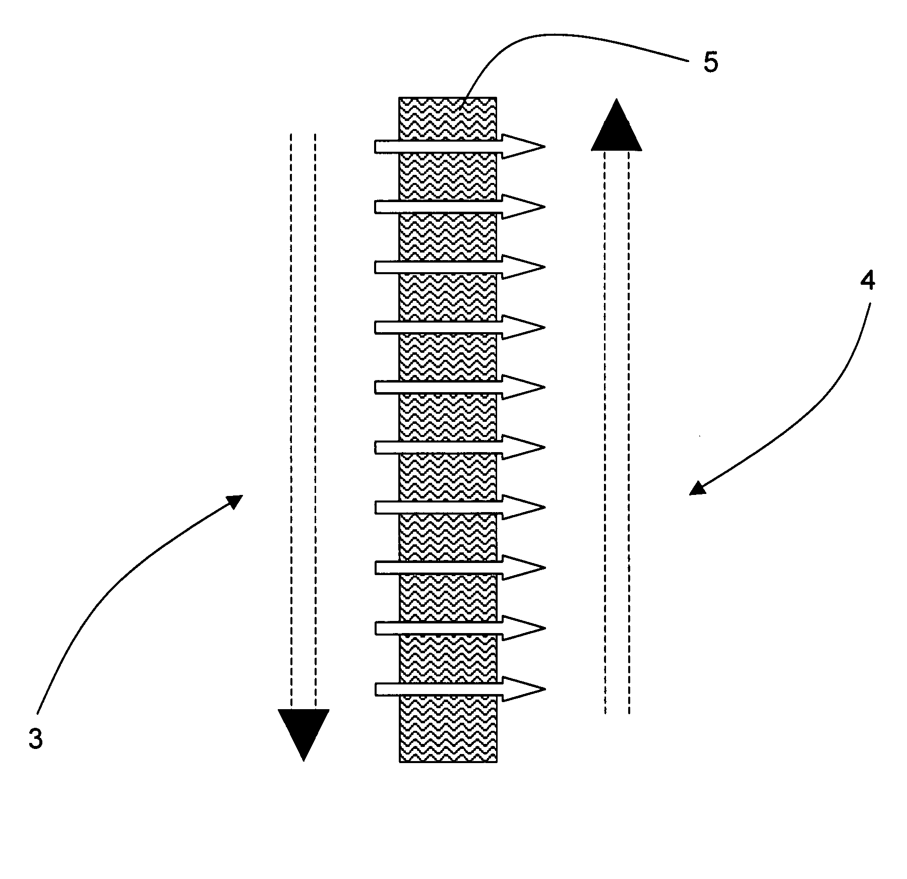
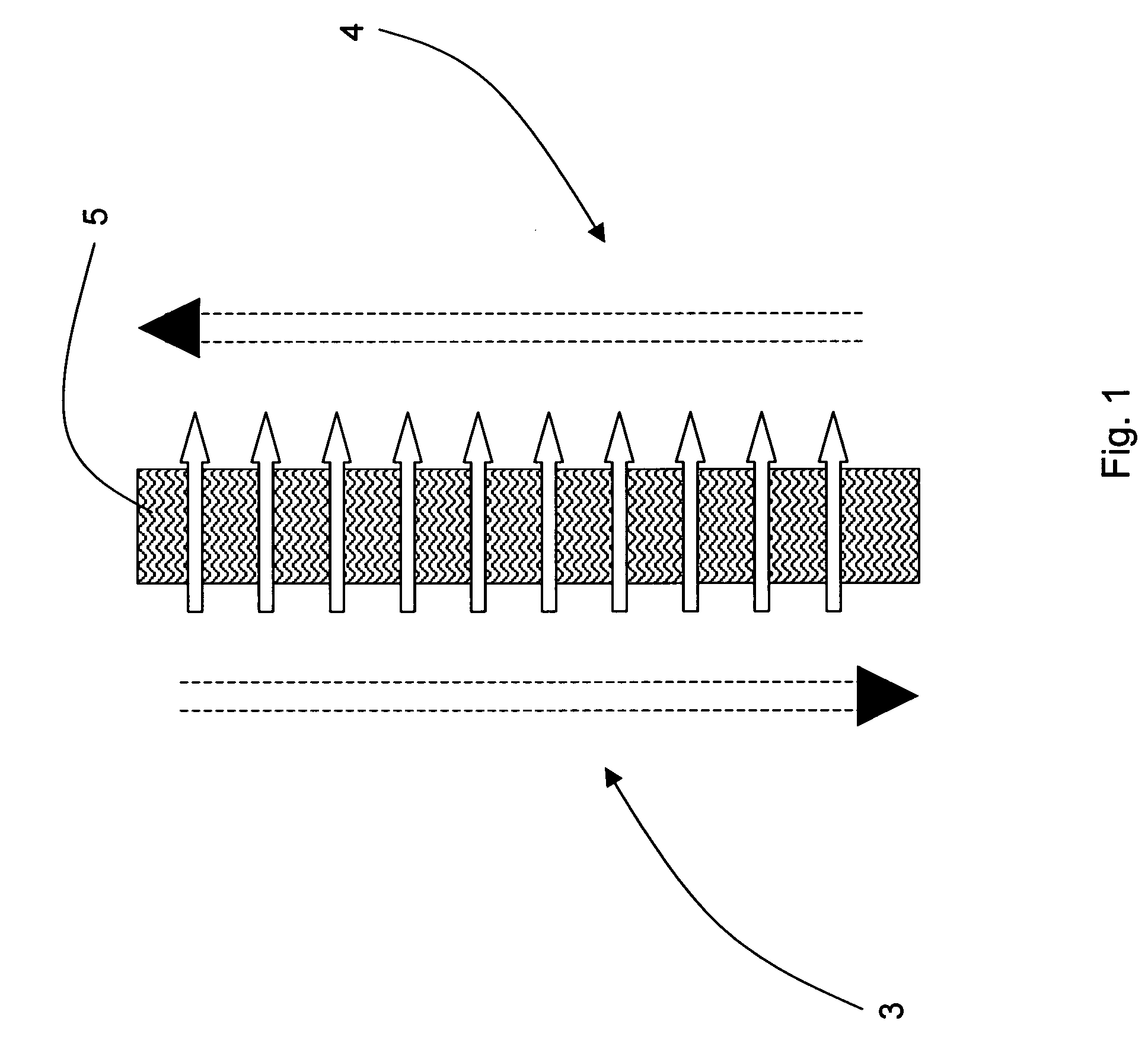
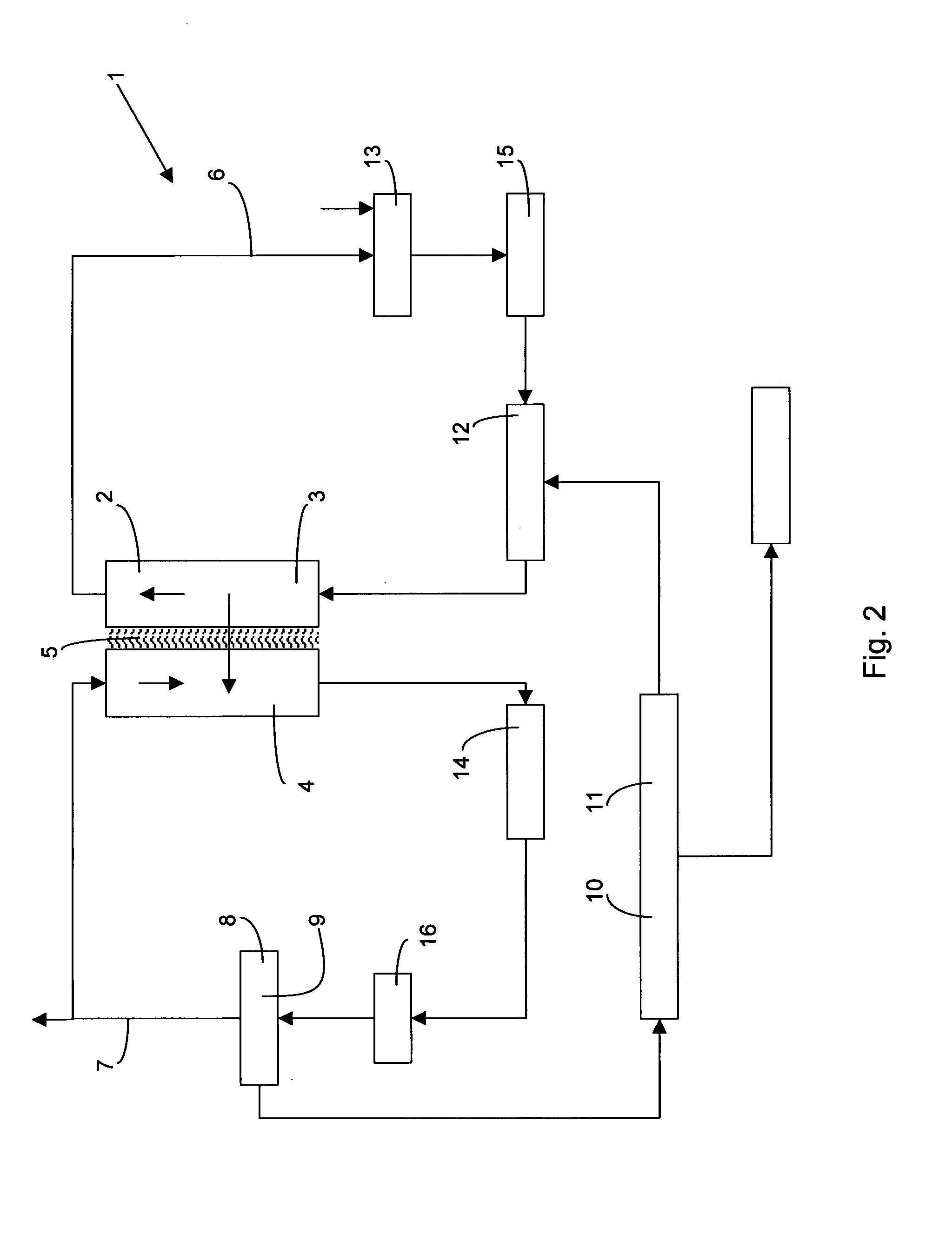
[0098]A bench-scale MD process was adapted according to the present invention for concentrating glucose (shown schematically in FIGS. 2 and 3), and was operated at the following conditions:[0099]Feed fluid inlet temperature −Tfi=40° C.[0100]Permeate inlet temperature −Tpi=20° C.[0101]Velocities of the feed fluid ωf=0.6 m·s−1 [0102]Velocities of the permeate fluid ωf=0.5 m·s−1 [0103]Feed fluid was a glucose solution at 30% (w / w)[0104]Membrane module HL50 (Siemens Water Technologies, Australia)[0105](FIG. 4 note: Tfo=temperature of the feed outlet, and Tpo, is the temperature of the permeate outlet)

[0106]A glucose solution was concentrated from 30 to 60% (w / w) (4.2 kg of glucose) over approximately 13 hours (this time would be shorter if a module with larger membrane area was available). The temperature change of the ...


PUM

PropertyMeasurementUnit
temperatureaaaaaaaaaa
vapour pressureaaaaaaaaaa
temperatureaaaaaaaaaa

Abstract

The present invention relates to a method and apparatus for concentrating a fluid with improved energy efficiency. The method comprises the steps of: providing a membrane distillation unit having an evaporation side in fluid communication with a first reservoir for containing the fluid, and a condensation side being in fluid communication with a second reservoir for containing a coolant; evaporating at least a portion of the fluid and condensing the fluid in the second reservoir. The method further comprises the steps of controllably transferring heat from the coolant to the fluid such that the temperature of the fluid is maintained at a predetermined temperature.

Description

FIELD OF THE INVENTION[0001]The present invention relates to a method and apparatus for concentrating fluids, and will be described hereinafter with reference to this application. However, it will be appreciated that the invention is not limited to this particular field of use.BACKGROUND OF THE INVENTION[0002]The following discussion of the prior art is provided to place the invention in an appropriate technical context and enable the advantages of it to be more fully understood. It should be appreciated, however, that any discussion of the prior art throughout the specification should not be considered as an express or implied admission that such prior art is widely known or forms part of common general knowledge in the field.[0003]Many commercially important products in a variety of industries are produced at low solids content. For example, in the pharmaceutical industry certain biomolecules, such as proteins, are produced at concentrations of around 1 to 10%. Other examples in t...

Claims


Application Information

Patent Timeline
Patent Type & Authority Applications(United States)
IPC IPC(8): B01D61/36
CPCA23L2/08B01D61/364B01D2313/38B01D71/32B01D2313/243B01D71/26Y02A40/963B01D2313/221
Inventor NGUYEN, MINH H.BUI, ANH VIET
Owner UNIVERSITY OF WESTERN SYDNEY
Why Eureka
Try Eureka