Method and apparatus for controlling the valve position of a variable orifice flow meter

a flow meter and variable orifice technology, applied in the direction of ratio control, process and machine control, instruments, etc., can solve the problems of large error terms that require a large change in signal, control loop, user producing faulty or suboptimal products, etc., to improve the response time of flow control loop, improve control response, and change the cross sectional area of the orifice

Inactive Publication Date: 2007-01-18
RIVATEK
View PDF22 Cites 25 Cited by
  • Summary
  • Abstract
  • Description
  • Claims
  • Application Information

AI Technical Summary

Benefits of technology

[0013] The present invention generally relates to fluid flow metering and control systems; more particularly relates to improving the response time of a flow control loop; and even more particularly improves the control response to changes in the flow setpoint, as well as to changes in the operating conditions (loop pressure) of the control system and loop. One aspect of the invention relates to a method of metering fluid flow through a variable orifice. A preferred environment in which the present invention is employed includes controlling the physical position of a restrictive member within the variable orifice, thereby changing the cross sectional area of the orifice.

Problems solved by technology

Small error terms require a small change in the signal that drives the valve, and large error terms will require a large change in the signal that drives the valve.
However, since control loops must be stable to ensure production processes continue to operate properly and safely, control loop speed is typically sacrificed for loop stability.
The longer the flow control loop deviates from the set point or optimum control value, the longer a user has to wait to start a production process, or worse, the longer the user is producing faulty or suboptimum product.
For example, a user may be producing or using very expensive chemicals in the production process, and so may have to discard the chemicals produced while the loop is not at the correct set point.
More specifically, generally the device does not monitor the inlet pressure, the outlet pressure, or the size of the opening of the valve orifice.
However, a drawback to using this method in a flow control loop is that the loop will respond differently for different inlet and outlet pressures and opening sizes of the valve.
Also, this setpoint modeling scheme does not improve the control loop response to changes in the loop operating conditions.
However, this scheme has some of the same drawbacks as the optimization scheme discussed above.
This method may be appropriate if a control loop has a known type of disturbance that occurs, and this disturbance results in causing the loop output to deviate from the desired output for an unacceptably long time.
One drawback to using feedforward disturbance correction is that the feedforward signal is only a correction signal.
Also, the feedforward signal is only correcting for one measured loop disturbance.

Method used


Image

  • Method and apparatus for controlling the valve position of a variable orifice flow meter
  • Method and apparatus for controlling the valve position of a variable orifice flow meter
  • Method and apparatus for controlling the valve position of a variable orifice flow meter

Examples


Embodiment Construction

.

[0020] The advantages and features which characterize the invention are pointed out with particularity in the claims annexed hereto and forming a part hereof. For a better understanding of the invention, however, reference should be made to the drawings which form a part hereof and to the accompanying descriptive matter, in which there is illustrated and described a preferred embodiment of the invention.

BRIEF DESCRIPTION OF THE DRAWINGS

[0021] The illustrative embodiments may best be described by reference to the accompanying drawings where:

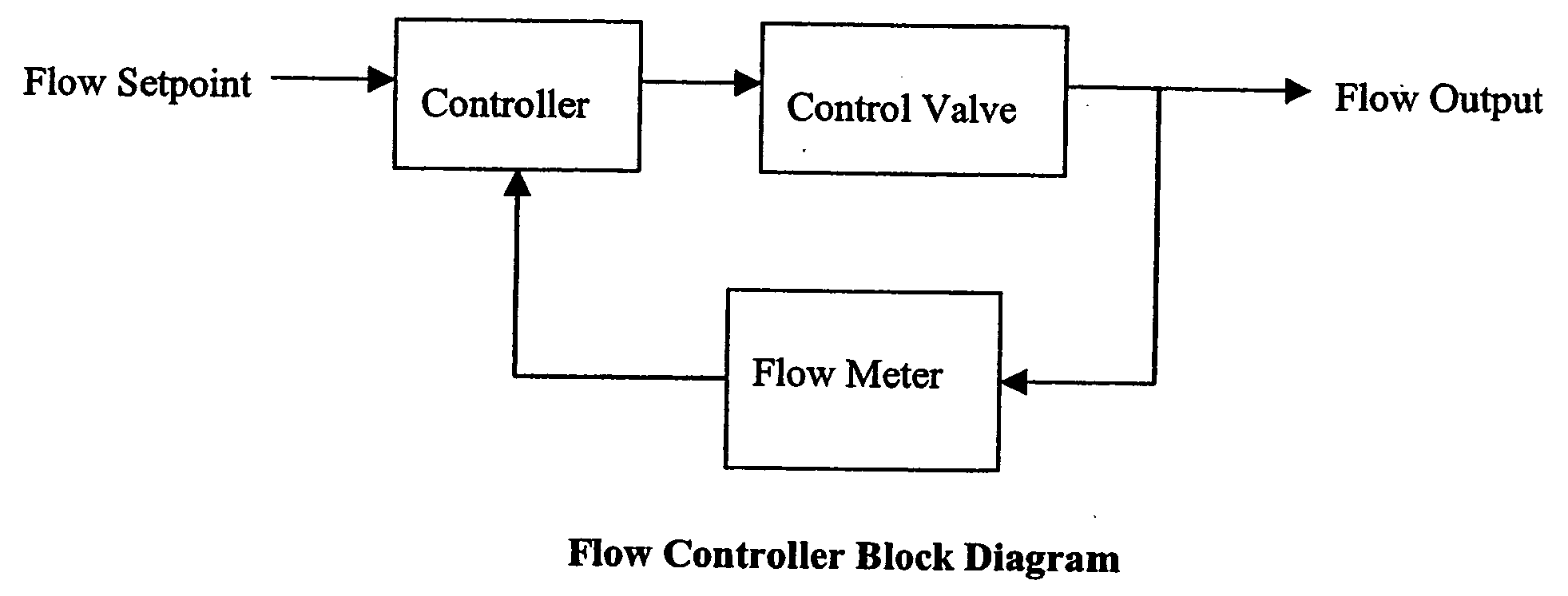
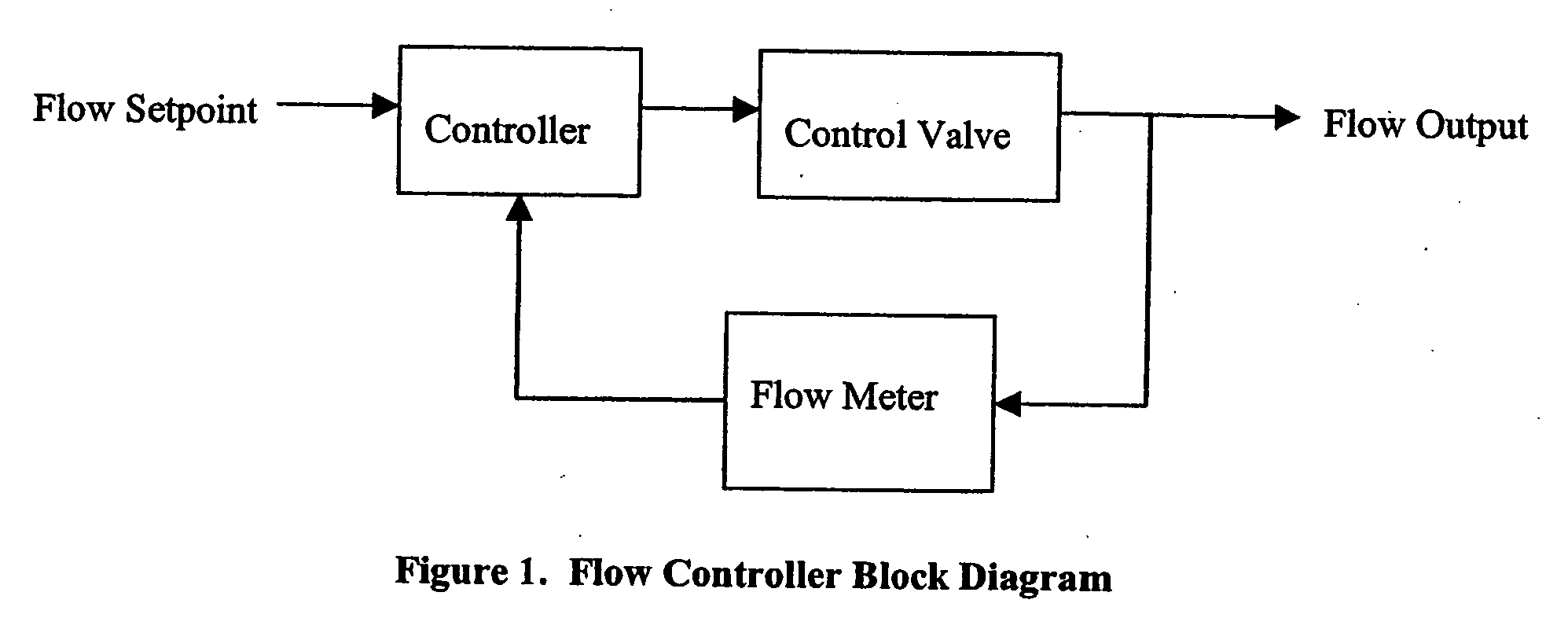
[0022]FIG. 1 is a block diagram illustrating the elements of a prior art flow control loop.

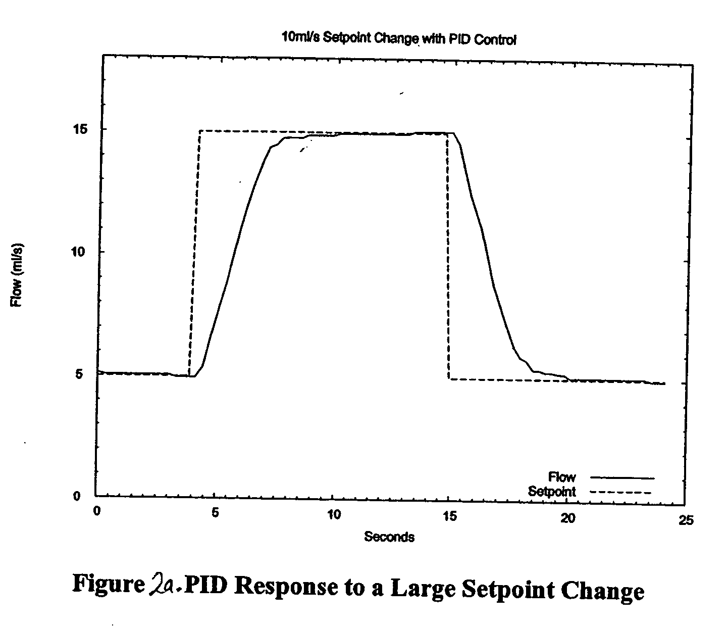
[0023]FIG. 2a is a diagram illustrating a representative PID response to a large setpoint change.

[0024]FIG. 2b is a diagram illustrating a representative PID response to a small setpoint change.

[0025]FIG. 2c is a diagram illustrating a representative PID response to a large control loop condition change.

[0026]FIG. 2d is a diagram illustrating a repres...


PUM


Abstract

A device for metering fluid flow is disclosed. The device includes a variable sized orifice defined by a fluid flow conduit and an element movable relative to the fluid flow conduit to vary a size of the orifice, a pressure sensor configured to determine a pressure differential across the orifice and generate a pressure signal, a positioning device configured to determine a position of the element relative to the conduit and generate a position signal, and a processor configured to determine the fluid flow rate using the pressure signal and the position signal. The system can directly control the adjustable valve or orifice. Alternatively, the system can move back and forth between a direct mode and a PID mode. When in a PID mode, the system employs a standard PID algorithm with a variable gain term. The system switches to direct mode when it is advantageous for the controller to directly change the valve position based upon the setpoint, and the input and output pressures.

Description

FIELD OF THE INVENTION [0001] The present invention generally relates to fluid flow metering and fluid control systems; more particularly relates to improving the response time of a flow control loop and system; and even more particularly improves the control response to changes in a flow setpoint, as well as to changes in the operating conditions (loop pressure) of the control loop. BACKGROUND [0002] In flow control systems, a valve may be controlled by an intelligent controller or other CPU based device (e.g., a personal computer). The controller device typically executes some form of a PID (proportional, integral, differential) algorithm to perform the flow control. As an input of the control loop, oftentimes a flow meter provides a flow rate. The controller continuously monitors the flow rate and compares it to a desired flow rate (e.g., the set point). The difference between the actual flow rate and the set point is commonly referred to as the error term. The signal that the co...

Claims


Application Information

Patent Timeline
Patent Type & Authority Applications(United States)
IPC IPC(8): G05D7/00G05D11/00
CPCG05D7/0635
Inventor EDWARDS, GRANT BRADLEYKIELB, JOHN ALLANNUGENT, DALE ALAN
Owner RIVATEK
Why Eureka
Try Eureka