Hydraulic control unit

a control unit and hydraulic technology, applied in the direction of valve operating means/releasing devices, vehicle sub-unit features, etc., can solve the problems of increasing the energy required to open the valve, increasing the oil pressure in the hydraulic chamber, and worsening of the oil leakage of the spool valve, so as to improve the energy efficiency of the belt-driven continuously variable transmission.

Inactive Publication Date: 2015-05-28
TOYOTA JIDOSHA KK
View PDF3 Cites 7 Cited by
  • Summary
  • Abstract
  • Description
  • Claims
  • Application Information

AI Technical Summary

Benefits of technology

[0015]The hydraulic control unit of the present invention may be applied to a belt-driven continuously variable transmission to control hydraulic pressure applied to the pulleys. In this case, energy efficiency of the belt-driven continuously variable transmission can be improved by preventing a leakage of highly pressurized fluid.

Problems solved by technology

In addition, a larger electricity is required to open the valve.
That is, oil leakage from the spool valve is worsened with a rise in the oil pressure in the hydraulic chamber.
For this reason, an energy loss may be increased.
Consequently, an opening response of the valve element may be worsened, that is, a control response may be worsened.

Method used


Image

  • Hydraulic control unit
  • Hydraulic control unit
  • Hydraulic control unit

Examples


Embodiment Construction

)

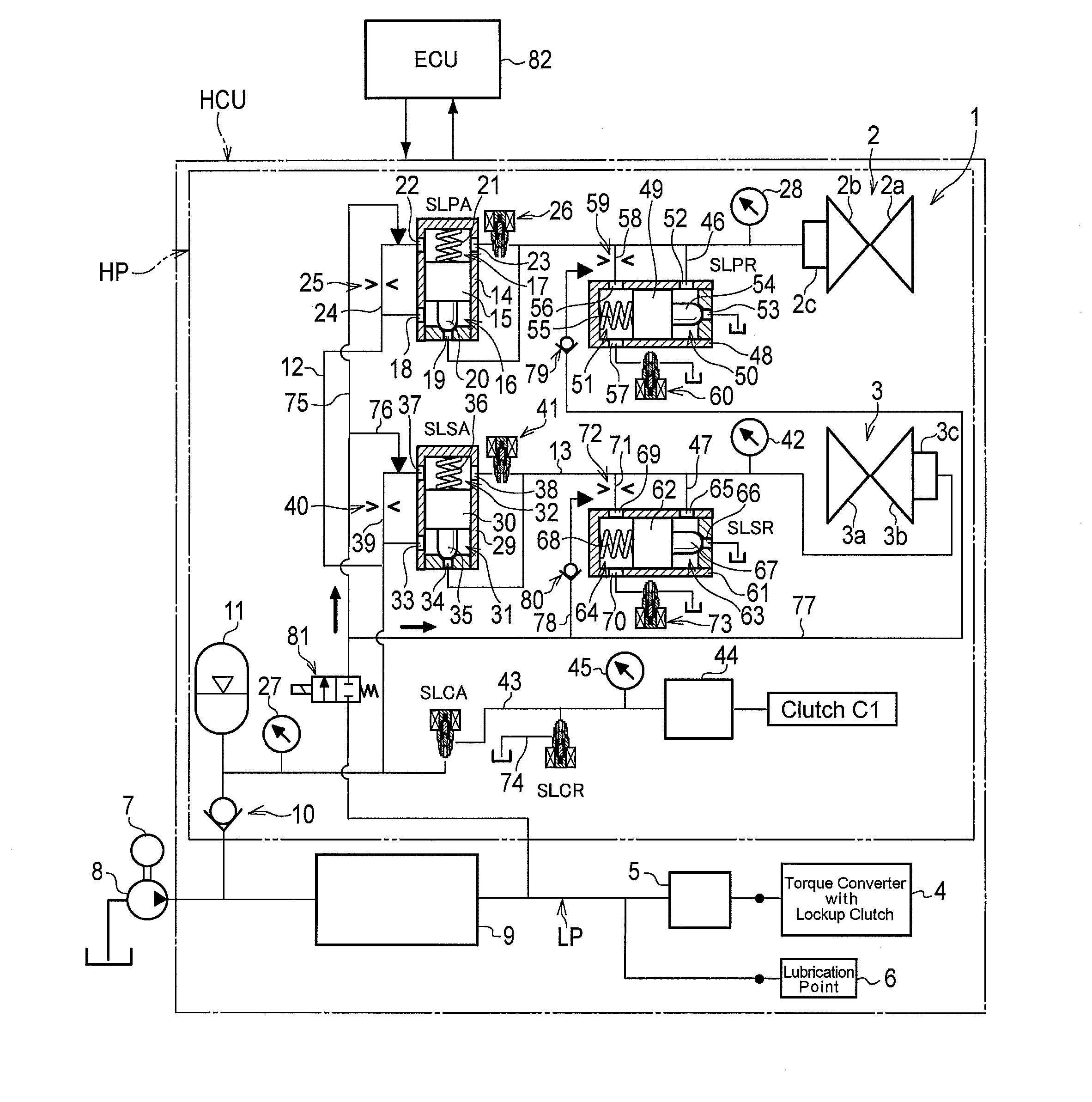
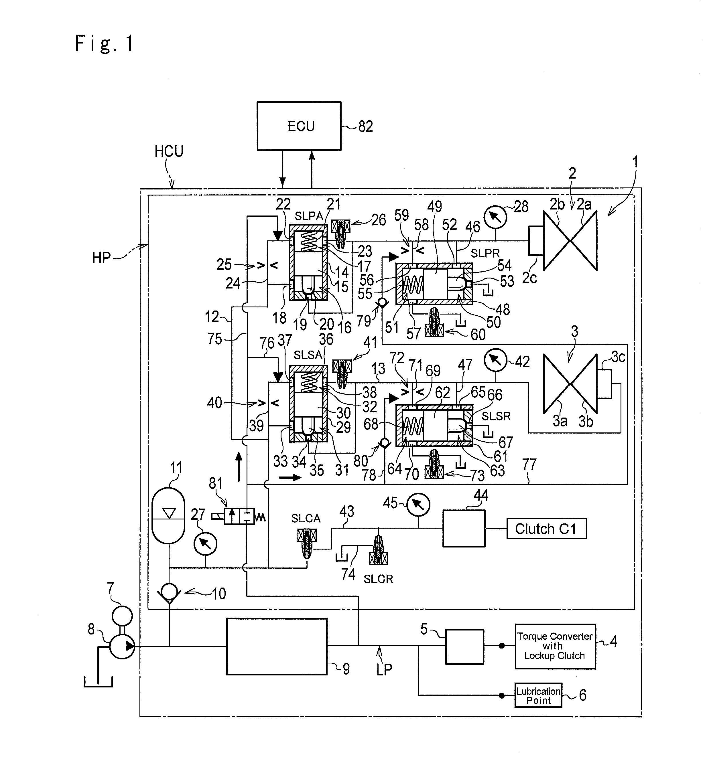
[0020]The hydraulic control unit HCU of the present invention may be applied not only to a transportation carrier such as an automobile and an air craft but also to a various kinds stationary industrial machineries. FIG. 1 shows a preferred example of applying the hydraulic control unit HCU to a conventional belt-driven continuously variable transmission 1 widely used in automobiles. A structure of the continuously variable transmission 1 will be briefly explained hereinafter. The continuously variable transmission 1 is comprised of a drive pulley 2 and a driven pulley 3. Specifically, the drive pulley 2 is comprised of a fixed sheave 2a and a movable sheave 2b allowed to reciprocate toward and away from the fixed sheave 2a, and a V-groove is formed between those sheaves 2a and 2b. Likewise, the driven pulley 3 is comprised of a fixed sheave 3a and a movable sheave 3b allowed to reciprocate toward and away from the fixed sheave 3a, and a V-groove is formed between those sheaves 3a ...


PUM


Abstract

A hydraulic control unit is provided. A valve is comprised of a piston having a valve element, a cylinder holding the piston while allowing to reciprocate axially, a positive pressure chamber formed on one side of the piston to which pressure to open the valve is applied, a back pressure chamber formed on the other side of the piston to which the pressure to close the valve is applied, and a connection passage for differentiating pressures in the positive pressure chamber and the back pressure chamber. A pilot valve selectively connects the back pressure chamber with a site where the pressure is lower than that of the back pressure chamber. Hydraulic pressure lower than that applied to positive pressure chamber is applied to a low pressure section. The hydraulic control unit comprises a means to deliver the fluid from the low pressure section to the back pressure chamber if an opening motion of the valve is slower than a predetermined reference value, by opening the pilot valve to connect the back pressure chamber with the low pressure section.

Description

TECHNICAL FIELD[0001]The present invention relates to a hydraulic control unit provided with a balance piston valve, in which a positive pressure chamber and a back pressure chamber are formed across a piston, and in which the piston is actuated according to a pressure deference between the positive pressure chamber and the back pressure chamber to open or close the valve.BACKGROUND ART[0002]In general, a speed ratio, a torque capacity and so on of a vehicular transmission is changed hydraulically. For example, a control unit for a belt-driven continuously variable transmission is described in Japanese Patent Laid-Open No. 2011-163393. The control unit is comprised of a pressure delivery valve for delivering an oil pressure to an oil chamber of a drive pulley, a pressure drain valve for draining an oil pressure from the oil chamber, a pressure delivery valve for delivering an oil pressure to an oil chamber of a driven pulley, and a pressure drain valve for draining an oil pressure f...

Claims


Application Information

Patent Timeline
Patent Type & Authority Applications(United States)
IPC IPC(8): F16H61/02F16H61/14
CPCF16H61/0251F16H2061/0253F16H2061/145F16H61/143B60Y2400/72F16H61/00F16H61/66259F16H61/66272Y10T137/7761
Inventor INAGAKI, TAKAFUMIHATTORI, YUJIINAGAWA, TOMOKAZUKIMURA, KENTANAGASATO, YU
Owner TOYOTA JIDOSHA KK
Why Eureka
Try Eureka