Method and apparatus for storing thermal energy

a technology of thermal energy and storage method, which is applied in the direction of lighting and heating apparatus, regenerative heat exchangers, heat storage plants, etc., can solve the problems of increasing the pressure loss of htf generated across the thermal store, the amount of cold energy remaining in the process air exhausted, and the effect of reducing the cross-sectional flow area

Active Publication Date: 2013-09-19
HIGHVIEW ENTERPRISES LTD
View PDF10 Cites 20 Cited by
  • Summary
  • Abstract
  • Description
  • Claims
  • Application Information

AI Technical Summary

Benefits of technology

[0103]The devices and methods of the present invention are capable of operating at different charging and discharging rates, i.e. the HTF can have a different flow rate through the thermal masses when charging the device to that when discharging the device. The charging phase may be of a longer duration than the discharging phase. Alternatively, the charging phase may be of a shorter duration than the discharging phase. The HTF flow rate can also be varied during the charging and discharging phases to maximise the thermal efficiency of the store, in particular at the end of the charging or discharging process where end effects can be significant. For example, significant deviation of the outlet temperature from the temperature observed during most of either the charge or discharge phases of the cycle can be reduced by increasing the flow rate towards the end of the charging or discharging phase of the cycle.
[0104]Consequently, the thermal energy storage device and method of the present invention have the capability to vary the available thermal mass cross-sectional area or particle size between charging and discharging to match the thermal and flow performance of the store. The device and method also have the capability to reduce the cross-sectional flow area or particle size near the output end of the store to minimise end-losses caused by the low flow rate part of the cycle.
[0105]The provision of at least three separate thermal masses with different aspect ratios and / or mean particle sizes means that the HTF flow area during charging and discharging can be varied to match the thermal and flow performance of the store. In addition, a reduced flow area at the output end of the store can be chosen to minimise end effects caused during a reduced flow-rate part of the discharge cycle.

Problems solved by technology

A major constraint to the efficiency of such cryogenic energy storage systems is the amount of cold energy remaining in the process air exhausted from the expansion turbine following expansion.
However, such features increase the friction between the solid thermal mass and the HTF and hence increase pressure losses in the HTF generated across the thermal store.
In that case, a fixed geometry store would suffer either poor thermal performance during discharging or unacceptably high pressure loss during charging.
However, such a small aspect ratio leads to high ‘end losses’ during the charging and discharging of the store: during charging, the thermal energy from the HTF cannot be completely captured unless an over-long store is used.
This is undesirable as the final section of the store near the output of the store is not fully charged and thermal energy flows between the charged and partially charged sections during the storage phase of the cycle, resulting in a degradation of thermal efficiency.
A similar problem is encountered during discharge; as the store discharges, the outlet temperature deviates from the storage temperature at the end of the cycle and it is not possible to fully discharge the final section of the store near the outlet without, again, resulting in a loss of thermal efficiency.

Method used


Image

  • Method and apparatus for storing thermal energy
  • Method and apparatus for storing thermal energy
  • Method and apparatus for storing thermal energy

Examples


Embodiment Construction

[0121]In a preferred embodiment, the present invention addresses the needs identified above by providing a thermal energy storage device and method in which the aspect ratio (flow area to length) for the charging and discharging phases of the store can be varied.

[0122]For example, in the case of a thermal store in a cryogenic energy storage system, a 4 hour charging period is typically required for a 20 hour discharge period. Therefore, the flow rates during the charging period will typically be five times larger than those during the discharge period and it is desired to provide a system with optimum properties during both charge and discharge.

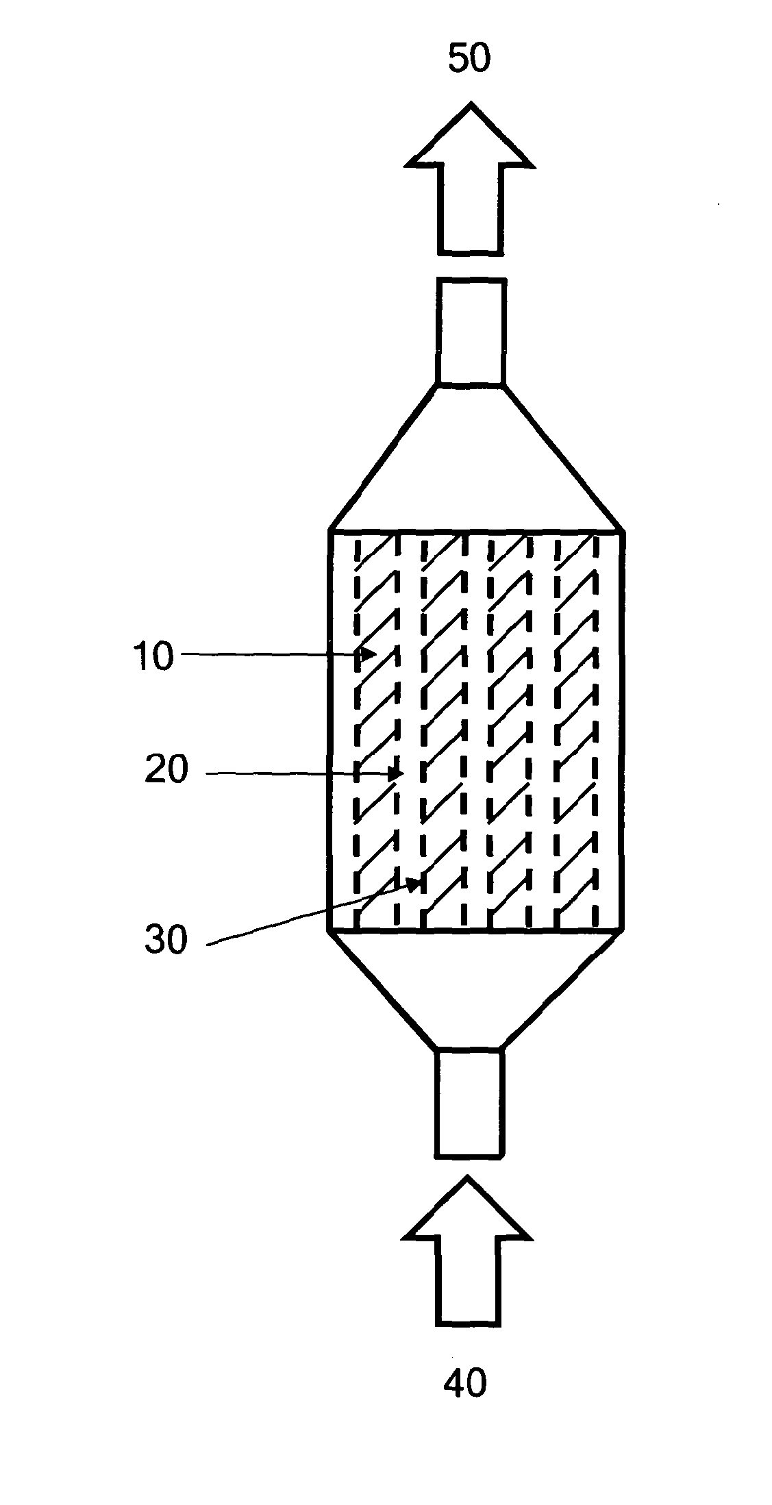
[0123]In the case of a cryogenic energy storage system, the thermal masses are cooled down during the charging process and then cold gas is extracted from the store during the discharge process. The following detailed description is specific to a cryogenic energy storage system. However, the disclosed thermal storage device and method could e...


PUM

PropertyMeasurementUnit
aspect ratioaaaaaaaaaa
aspect ratiosaaaaaaaaaa
thermalaaaaaaaaaa

Abstract

Methods and apparatus for storing thermal energy are disclosed. The thermal energy may be hot or cold. The methods and apparatus allow the thermal store to be charged and discharged at different rates. The methods and apparatus also allow the thermal store to be charged and discharged with multiple and/or interrupted phases.

Description

FIELD OF THE INVENTION[0001]The present invention relates to methods and apparatus for storing thermal energy.BACKGROUND OF THE INVENTION[0002]Thermal energy storage devices (or thermal stores) are used to receive and then store heat, cold, or thermal energy for a period of time until it is needed for a useful purpose. Such thermal storage devices allow high or low (including cryogenic) temperature energy to be temporarily stored for later use, and offer the possibility of storing thermal energy, for example, for later conversion to electricity, for use in an air liquefaction process to reduce the energy consumed by the process, or to provide cooling for co-located processes. It is known to store thermal energy by increasing or decreasing the temperature of a substance, by changing the state (i.e. solid, liquid, or gas) of a substance, or by a combination of the two.[0003]A thermal store typically operates on a three phase thermal storage process: charge, store and discharge. FIG. 1...

Claims


Application Information

Patent Timeline
Patent Type & Authority Applications(United States)
IPC IPC(8): F28D17/00F28D20/00
CPCF28D20/028Y02E60/142F28D20/0056F28D17/00F28D20/026F28D2020/0082F28D2020/006F28D2021/0033F28D20/00Y02E60/145F28F27/02Y02E10/46Y02E60/14F28D20/02
Inventor MORGAN, ROBERTDEARMAN, MICHAEL
Owner HIGHVIEW ENTERPRISES LTD
Why Eureka
Try Eureka