
Sheet workpiece phased array ultrasonic guided wave imaging detection system and detection method thereof

An ultrasonic guided wave and imaging detection technology, which is used in the analysis of solids using sonic/ultrasonic/infrasonic waves, and can solve the problem of inability to observe scanning images at the same time.

Active Publication Date: 2015-04-22
GUANGDONG GOWORLD
View PDF4 Cites 18 Cited by
  • Summary
  • Abstract
  • Description
  • Claims
  • Application Information

AI Technical Summary

Problems solved by technology

[0003] The key component of the guided wave detection is the ultrasonic guided wave probe. The traditional ultrasonic guided wave probe has a single-chip probe structure. The single-chip probe generates a beam of guided waves. The detection coverage is an acoustic beam line, which is realized by moving the single-chip probe. Due to the coverage of the area, scanning images of a certain area cannot be observed at the same time; or a ring-shaped multi-chip probe is used, and all the chips of the probe are simultaneously excited to generate multiple beams of guided waves to detect within a certain area, but this application is mainly used for pipeline inspection , and the detection generally does not use the phased array focusing method

Method used


Image

  • Sheet workpiece phased array ultrasonic guided wave imaging detection system and detection method thereof
  • Sheet workpiece phased array ultrasonic guided wave imaging detection system and detection method thereof
  • Sheet workpiece phased array ultrasonic guided wave imaging detection system and detection method thereof

Examples


Embodiment Construction

[0034] Further description will be given below in conjunction with the accompanying drawings and preferred embodiments of the present invention.

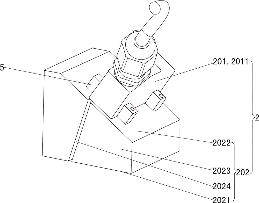
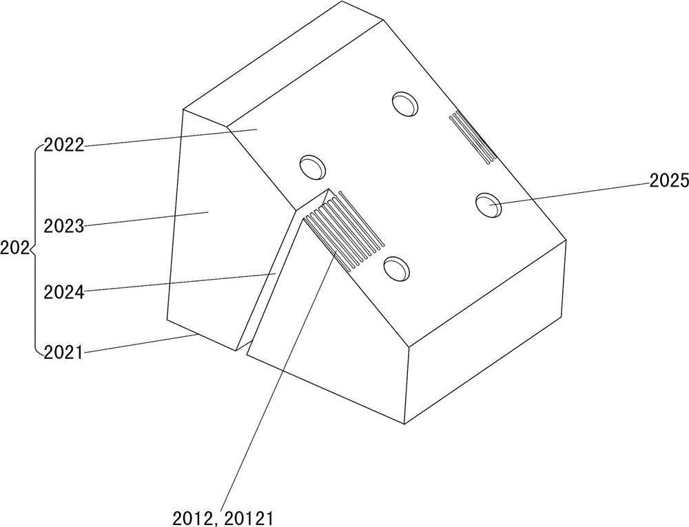
[0035] Such as Figure 1 to Figure 5 As shown, this thin plate workpiece phased array ultrasonic guided wave imaging detection system includes a phased array ultrasonic detector 1, a phased array ultrasonic guided wave probe 2, a position encoder 3 and imaging software 4; the position encoder 3 is installed in On the phased array ultrasonic guided wave probe 2, the phased array ultrasonic guided wave probe 2 and the position encoder 3 are electrically connected to the phased array ultrasonic detector 1; the imaging software 4 is installed in the phased array ultrasonic detector 1; The controlled array ultrasonic guided wave probe 2 includes a phased array ultrasonic probe 201 and an ultrasonic guided wave wedge 202; the ultrasonic guided wave wedge 202 has a bottom surface 2021, an inclined surface 2022 opposite to the bottom surfac...


PUM


Abstract

The invention relates to a sheet workpiece phased array ultrasonic guided wave imaging detection system and a detection method of the system. The system comprises a phased array ultrasonic detector, a phased array ultrasonic guided wave probe and a position encoder. The phased array ultrasonic guided wave probe comprises a phased array ultrasonic probe body and an ultrasonic guided wave wedge, an inclined rectangular groove is formed in the vertical side face of the ultrasonic guided wave wedge, the phased array ultrasonic probe body further comprises a probe main body and array wafers, the phased array ultrasonic probe body is installed on the inclined face of the ultrasonic guided wave wedge, the phased array ultrasonic probe body is tightly combined with the ultrasonic guided wave wedge through a coupling agent, and the array wafers are distributed on the inclined face in the depth direction of the inclined rectangular groove. The ultrasonic guided wave wedge and the array wafers are adopted for large-area detection, so that detection efficiency is improved, edges of detection areas are covered with each other in an overlapped mode, and detection results are more accurate; the inclined rectangular groove is formed to generate a coupling monitoring signal and a detection signal which are matched with each other so that defects of sheet workpieces can be judged, and accuracy of the detection results is further improved.

Description

technical field [0001] The invention relates to an ultrasonic detection device, in particular to a thin-plate workpiece phased array ultrasonic guided wave imaging detection system and a detection method thereof. Background technique [0002] For thin-plate workpieces, it is very difficult to use traditional ultrasonic flaw detection methods such as transverse wave oblique incident primary wave and secondary wave flaw detection, or longitudinal wave vertical incident flaw detection, but ultrasonic guided waves are very suitable for large-area rapid detection of thin plate workpieces. The generation mechanism is that the ultrasonic waves reciprocate and reflect repeatedly in a space-limited medium, and further produce complex superposition interference and geometric dispersion. [0003] The key component of guided wave detection is the ultrasonic guided wave probe. The traditional ultrasonic guided wave probe has a single-chip probe structure. The single-chip probe generates ...

Claims


Application Information

Patent Timeline
IPC IPC(8): G01N29/06
Inventor 付汝龙陈建华林齐梅林丹源彭斯婷詹红庆陈伟
Owner GUANGDONG GOWORLD
Learn More