Self-balanced quick load-reducing control method for microgrid

A control method and micro-grid technology, applied in the integration of power network operating system, AC network voltage adjustment, reducing/preventing power oscillation, etc., can solve the problems of micro-grid frequency collapse, load shedding error, small rotational inertia, etc.

Inactive Publication Date: 2015-04-22
STATE GRID CORP OF CHINA +3
View PDF3 Cites 22 Cited by
  • Summary
  • Abstract
  • Description
  • Claims
  • Application Information

AI Technical Summary

Problems solved by technology

When there is a power shortage, you must passively wait for the frequency to drop below the operating value, and a certain delay is required to prevent false switching
However, the capacity of the microgrid is small, the ratio of power shortage is large, the moment of inertia is small, and the frequency and voltage drop quickly. The traditional low-frequency load shedding action is too slow, which often leads to the frequency collapse of the microgrid.
[0006] The load shedding according to the rate of change of frequency (ROCOF) is too sensitive, and it is easy to malfunction when the system is disturbed or short-circuited.
Affected by system inertia changes, frequency and ROCOF measurement accuracy, the calculated load shedding has a large error
Once these calculation errors exceed the weak regulation ability of the microgrid, the frequency will continue to drop
[0007] The effect of interlocking load shedding on the frequency drop is obvious, but due to the inconsistency between the peak and valley changes of the power generation output and the load, the power deficit in the microgrid changes greatly, which is easy to cause over-cutting or under-cutting
Moreover, the operation mode of distributed power in the microgrid is relatively flexible. After disconnecting from the main grid, different types such as "power surplus type", "power deficit type" and "self-sufficiency type" may be formed. Adapt to various operating modes

Method used


Image

  • Self-balanced quick load-reducing control method for microgrid
  • Self-balanced quick load-reducing control method for microgrid
  • Self-balanced quick load-reducing control method for microgrid

Examples


Embodiment Construction

[0071] The present invention will be further described below in conjunction with the accompanying drawings and embodiments.

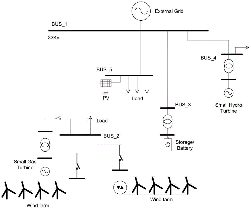
[0072] figure 1 It is a schematic diagram of a typical microgrid, including small hydropower units, gas turbines, wind farms, photovoltaic farms, energy storage batteries and partial loads.

[0073] 1. Estimate the disturbance magnitude of the microgrid online

[0074] The first stage is to estimate the magnitude of the disturbance in the microgrid, which includes two important steps, one is to determine the equivalent inertia constant of the microgrid, and the other is to calculate the power balance of the microgrid.

[0075] In a distribution network containing hybrid new energy generation, the inertia constant H can be defined by the following formula:

[0076]

[0077] But for different types of generators, the definition of inertia constant is different. H of synchronous generator SG

[0078]

[0079] Among them, J is the moment of inert...


PUM


Abstract

The invention discloses a self-balanced quick load-reducing control method for a microgrid. The method comprises the following steps: determining an equivalent inertia constant of the microgrid, calculating a power balance of the microgrid and evaluating the disturbance amplitude in the microgrid; lowering the changing speed of frequency respectively through frequency responsive active power control of an energy storage system and droop control of a wind turbine; and balancing the initial power vacancy in the microgrid by virtue of rotary kinetic energy, a load adjusting effect and a distributive power supply adjusting capacity, calculating power to be reduced according to the power balance, and obtaining the dynamic characteristics of the system frequency when no spinning reserve is available according to the requirement on load reducing time under various power vacancies. According to the method disclosed by the invention, when the microgrid operates independently and relatively great disturbance occurs in the microgrid, self-balanced load reduction is implemented to eliminate power unbalance in the microgrid by calculating the equivalent inertia constant of the microgrid and evaluating the disturbance amplitude in the microgrid on line.

Description

technical field [0001] The invention relates to a self-balancing rapid load reduction control method for a microgrid. Background technique [0002] Microgrids include distributed power sources such as wind power generation and photovoltaic power generation, energy storage and loads. The output of distributed power is intermittent and random. In the case of grid connection, the main grid can provide power support for the micro grid, and each distributed power can operate at the maximum power tracking point; Due to the power imbalance and load fluctuation, certain control measures need to be taken to ensure the power balance inside the microgrid and maintain the frequency and voltage stability inside the microgrid. [0003] The microgrid generally adopts a hierarchical control method. A sub-controller is installed at each distributed power outlet to collect the output power, frequency and frequency change rate of the distributed power outlet. The network receives the data up...

Claims


Application Information

Patent Timeline
Patent Type & Authority Applications(China)
IPC IPC(8): H02J3/24
CPCH02J3/14H02J3/24Y02B70/3225Y04S20/222
Inventor 刘知凡马红伟鞠洪新毛建容
Owner STATE GRID CORP OF CHINA
Why Eureka
Try Eureka