
Photovoltaic solar energy rotation support

A technology of photovoltaic solar energy and rotating bracket, applied in the field of photovoltaic solar energy, can solve the problems of inability to maximize the power generation efficiency of solar modules, adjust solar modules, complex structures, etc., and achieve manual and automatic operation, high adjustment accuracy, and convenient and simple operation Effect

Inactive Publication Date: 2015-04-22
KINGSHORE NEW RESOURCES ELECTRIC JIANGSU
View PDF0 Cites 23 Cited by
  • Summary
  • Abstract
  • Description
  • Claims
  • Application Information

AI Technical Summary

Problems solved by technology

However, since the inclination angle of the plane of the solar module cannot be adjusted, the angle of the solar module cannot be adjusted according to the change of the sun angle, so the power generation efficiency of the solar module cannot be maximized, and in the existing technology, although the angle can be adjusted, there is a structural Complexity, high cost, complicated operation and low precision

Method used


Image

  • Photovoltaic solar energy rotation support
  • Photovoltaic solar energy rotation support
  • Photovoltaic solar energy rotation support

Examples


Embodiment 1

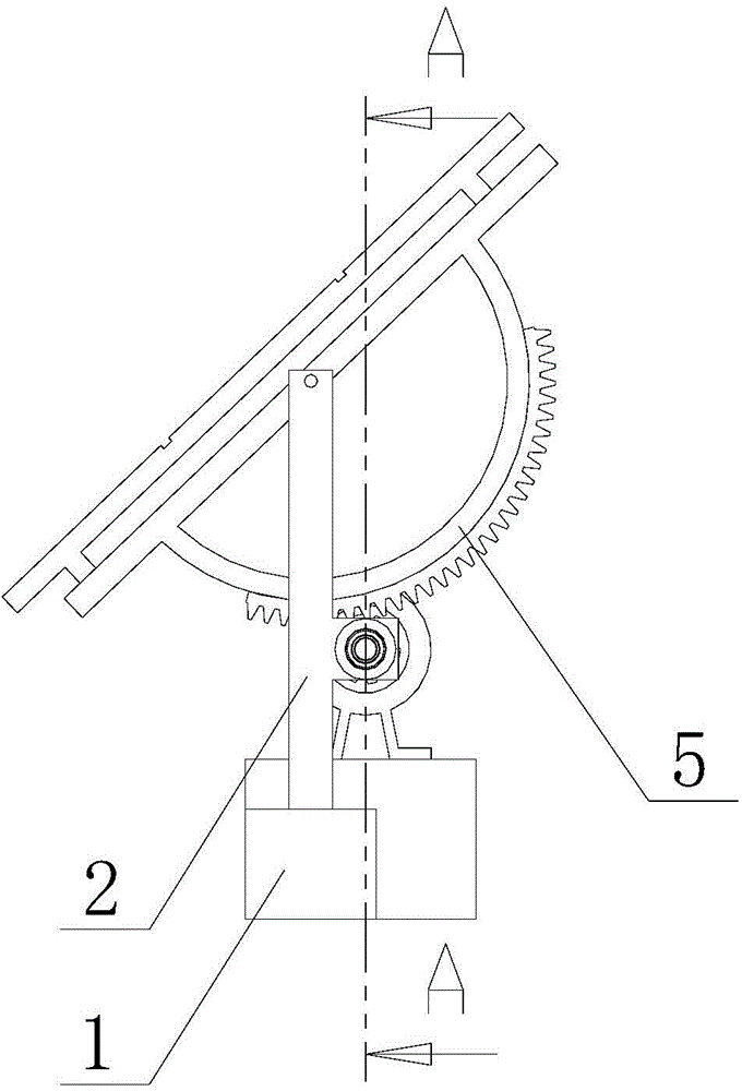
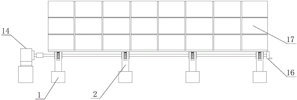
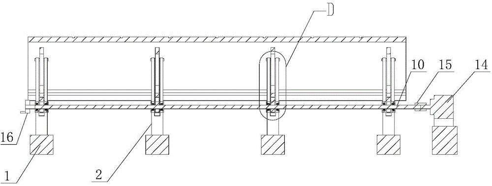
[0022] A photovoltaic solar rotating support provided in this embodiment includes four bases 1 arranged side by side. The upper end of the base 1 is provided with a column 2. The column 2 is provided with a U-shaped hole 3 along its length direction, and the upper end of the U-shaped hole 3 is also covered. There is a rotating shaft 4, and a photovoltaic rotating bracket 5 is set on the rotating shaft 4. The photovoltaic rotating bracket 5 is composed of a beam 6 and a semicircular frame 7 perpendicular to the beam 6. The center of the semicircular frame 7 is on the beam 6, and the rotating shaft 4 Pass through the center of the semicircle frame 7 to make the photovoltaic rotating bracket 5 rotate along the rotation axis 4, and an arc rack 8 is provided in the circumferential direction of the semicircle frame 7, and an arc rack 8 is provided on the column 2 in the horizontal direction at the lower end of the arc rack 8 The U-shaped bracket 9 is provided with a main shaft 10 on ...


PUM


Abstract

The invention discloses a photovoltaic solar energy rotation support which comprises at least two bases arranged side by side. Stand columns are arranged at the upper ends of the bases and provided with U-shaped holes in the length direction of the stand columns, and rotating shafts are further arranged at the upper ends of the U-shaped holes in a sleeved mode. A photovoltaic rotation support body is arranged on each rotating shaft in a sleeving mode and comprises a cross beam and a semicircular frame perpendicular to the cross beam, wherein the circle center of the semicircular frame is on the cross beam, the rotating shaft penetrates through the circle center of the semicircular frame so that the photovoltaic rotation support body can rotate around the rotating shaft, and a circular arc rack is further arranged in the circumference direction of the semicircular frame. U-shaped supports are further arranged on the part, located at the lower ends of the circular arc racks, on the stand columns in the horizontal direction, a main shaft is sleeved with the U-shaped supports and penetrates though the bases arranged side by side in sequence, gears are further arranged on the main shaft in a sleeving mode, and the gears are meshed with the circular arc racks. By means of the photovoltaic solar energy rotation support, overall simultaneous angle adjustment can be achieved, the adjusting time is short, the working efficiency is high, the adjusting precision is high, the utilization of solar energy is effectively improved, operation is convenient, and manual operation and automatic operation can be achieved.

Description

technical field [0001] The invention relates to photovoltaic solar energy, in particular to a photovoltaic solar rotating support. Background technique [0002] With the rapid development of the economy, the energy supply is becoming increasingly tense, and the application field of solar photovoltaic power generation as a new type of energy is expanding day by day. At present, fixed solar brackets are widely used in the construction of solar photovoltaic power generation systems, and the fixed brackets have a simple structure. However, since the inclination angle of the plane of the solar module cannot be adjusted, the angle of the solar module cannot be adjusted according to the change of the sun angle, so the power generation efficiency of the solar module cannot be maximized, and in the existing technology, although the angle can be adjusted, there is a structural Complexity, high cost, complicated operation and low precision. Contents of the invention [0003] The te...

Claims


Application Information

Patent Timeline
Patent Type & Authority Applications(China)
IPC IPC(8): H02S20/32
CPCH02S20/00F24S30/425F24S2030/134F24S2030/136Y02E10/47Y02E10/50
Inventor 朱冬宏钱纪明陈正国
Owner KINGSHORE NEW RESOURCES ELECTRIC JIANGSU
Learn More