An agricultural fertilization device

A fertilization device and agricultural technology, applied in the direction of fertilization device, application, agriculture, etc., can solve the problems affecting the timing of fertilizer spreading and closing, increasing the wear of clutch and shaft, reducing the service life of clutch, etc., so as to improve the efficiency of fertilization, Effect of reducing friction and prolonging service life

Active Publication Date: 2016-05-18
崔联富
View PDF8 Cites 0 Cited by
  • Summary
  • Abstract
  • Description
  • Claims
  • Application Information

AI Technical Summary

Problems solved by technology

[0002] Most of the existing fertilization devices are installed on the body of the walking tractor, and a single chain mechanism is used to make the power of the wheel shaft drive the fertilizer to work. Since the two sprockets in the chain mechanism need to be on the same parallel plane, the fertilizer box of the fertilization device with this structure The position is higher than the body of the walking tractor. Only one driving sprocket can be installed on the wheel shaft outside the wheel. The driving sprocket is connected with the driven sprocket through the chain, and the driven sprocket is fixedly connected with the fertilization shaft of the fertilizer applicator. Power transmission, so the fertilizer applicator is usually installed on the top of the frame, which affects the sight when working and driving, and is prone to danger; and the chain structure is easily affected by soil and weeds, which affects the work progress; the chain is placed on the outside of the tire Rotating, there are potential safety hazards; the high fertilizer box makes the center of gravity of the walking tractor move up, and it is easy to overturn when working on slopes; when working on land with different ridge spacing, the wheel width of the walking tractor needs to be adjusted. , it is necessary to disassemble the chain mechanism first, adjust the wheel width, and then reinstall the chain structure, which is very troublesome; and the fertilization clutch of the fertilization box is usually moved by a solid iron rod, and the clutch is often laborious and cannot be opened. It affects the timing of fertilizer application and closing, and the brute force operation also increases the wear between the clutch and the shaft, reducing the service life of the clutch; in summary, the structure of the

Method used


Image

  • An agricultural fertilization device
  • An agricultural fertilization device
  • An agricultural fertilization device

Examples


Embodiment Construction

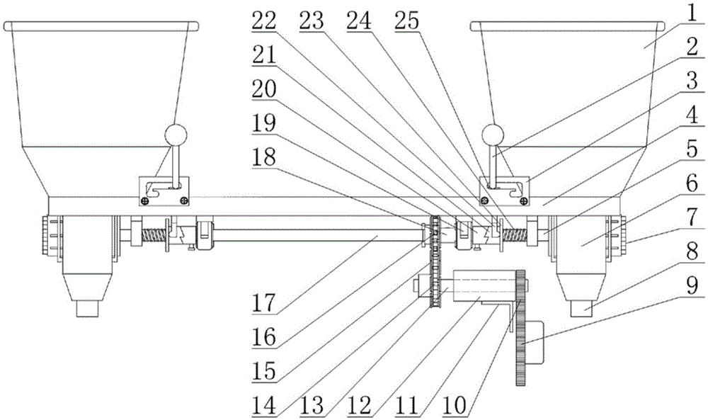
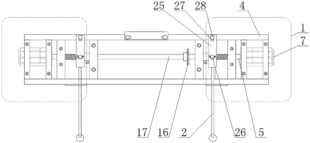
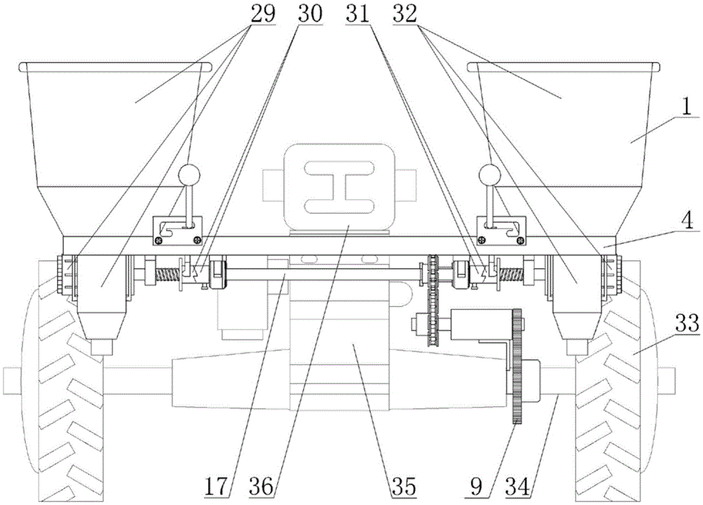
[0012] An agricultural fertilizing device, comprising a fertilizer applicator, a power transmission mechanism and a clutch mechanism, the power transmission mechanism transmits the power of the power source to the fertilizer applicator to make the fertilizer applicator work, and the power source is the wheel shaft 34 of a walking tractor, The power of the wheel shaft comes from the engine and gearbox of the walk-behind tractor, and the clutch mechanism can arbitrarily cut off or connect the power from the power source; The fertilization mechanism 6 is composed of a rotating fertilization wheel. The fertilization wheel is equipped with a fertilization adjustment wheel 7 on the outside of the fertilizer. The upper end of the fertilization wheel corresponds to the inside of the fertilizer box, and the lower end of the fertilization wheel corresponds to the fertilizer outlet 8. The fertilization outlet is covered with a bellows or hose. When the fertilization shaft drives the ferti...


PUM


Abstract

The invention relates to an agricultural fertilizer applying device. The agricultural fertilizer applying device comprises two fertilizer applying devices, a power transmission mechanism and two clutch mechanisms, wherein the power transmission mechanism is provided with a shaft sleeve, a driven sprocket, a driving sprocket, a chain, a power transmission rod, a rod sleeve, a driven gear and a driving gear fixedly connected with a wheel axle between two driving wheels of a walking tractor; each clutch mechanism is provided with a first end pipe, a second end pipe, a shifting fork, a shifting rod, a connecting plate and a spring. The agricultural fertilizer applying device has the advantages that power of the wheel axle can be transmitted to the fertilizer applying devices in an L shape, limitation of positions of wheels can be avoided, the power transmission mechanism can be arranged at the inner side of the wheels, and operation safety coefficient is improved; meanwhile, a mounting position of each fertilizer applying device can be customized, after moulting height of a fertilizer box is lowered, sight is wide when working, center of gravity also shifts down, and the walking tractor is more stable during sloping field operation and safe during travelling; and compared with a power transmission way of the traditional single chain mechanism, a structure that power of the wheel axle is transmitted to a chain mechanism by virtue of a power transmission rod by adopting the driving gear and the driven gear is more reliable.

Description

technical field [0001] The invention provides an agricultural fertilizing device, in particular to a fertilizing device used in conjunction with a walking tractor. technical background [0002] Most of the existing fertilization devices are installed on the body of the walking tractor, and a single chain mechanism is used to make the power of the wheel shaft drive the fertilizer to work. Since the two sprockets in the chain mechanism need to be on the same parallel plane, the fertilizer box of the fertilization device with this structure The position is higher than the body of the walking tractor. Only one driving sprocket can be installed on the wheel shaft outside the wheel. The driving sprocket is connected with the driven sprocket through the chain, and the driven sprocket is fixedly connected with the fertilization shaft of the fertilizer applicator. Power transmission, so the fertilizer applicator is usually installed on the top of the frame, which affects the sight wh...

Claims


Application Information

Patent Timeline
Patent Type & Authority Patents(China)
IPC IPC(8): A01C15/12A01C19/04
Inventor 崔记毓王晶崔程程崔联富
Owner 崔联富
Why Eureka
Try Eureka