Electric miter saw

A miter saw, electric technology, applied in the direction of sawing machine, metal sawing equipment, metal processing equipment, etc., can solve the long slide rail strength, high manufacturing precision requirements, shorten the working space and packaging volume, and the sliding stroke is very small Difficult to make too big and other problems, to achieve the effect of easy cutting and observation, saving working space and reducing packaging volume

Active Publication Date: 2014-05-28
SUMEC HARDWARE & TOOLS
View PDF4 Cites 0 Cited by
  • Summary
  • Abstract
  • Description
  • Claims
  • Application Information

AI Technical Summary

Problems solved by technology

Patent US5239906 and patent CN200410044804.8 disclose sliding miter saws. A swing arm is arranged at the end of the workbench. At least one slide rail is fixed on the swing arm toward the center of the workbench. The saw mechanism is slidably mounted on the slide rail. For cutting, this solution can effectively shorten the working space and packaging volume compared with the previous solution, but because the single-layer slide rail is used, it is difficult to make the sliding stroke too large, and the strength and manufacturing accuracy of the long slide rail are very high.
Patent EP0379322B1 discloses another sliding miter saw. There is a slide rail inside the workbench. One end of the slide rail is fixed with a swing arm, and the saw mechanism is installed on the swing arm. At the same time, a large working space is still required at the rear of the machine, and the packaging volume is large

Method used


Image

  • Electric miter saw
  • Electric miter saw
  • Electric miter saw

Examples


Embodiment Construction

[0045] The present invention will be further described below in conjunction with the accompanying drawings. The following examples are only used to illustrate the technical solution of the present invention more clearly, but not to limit the protection scope of the present invention.

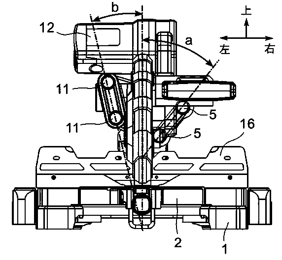
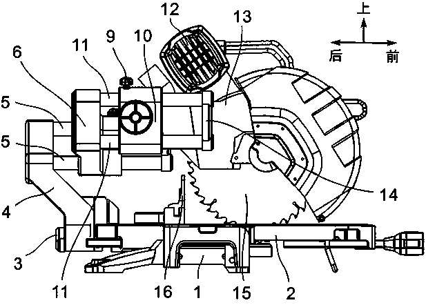
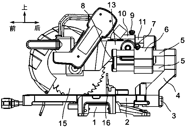
[0046] Such as figure 1 As shown in -4, the electric miter saw of the present invention includes a base 1, a grid 16 installed on the base 1 for positioning workpieces, a workbench 2 rotatably connected to the base 1, and rotatably installed at the end of the workbench 2 The swing arm 4. The swing arm 4 is fixed and locked on the workbench 2 through a swing arm lock button 3, so that the swing arm 4 and the workbench 2 rotate relative to each other to form a set cutting angle.

[0047]The swing arm 4 is provided with two parallel first-layer slide rails 5 extending forward in the horizontal direction, and the first-layer slide rail 5 is provided with a slider 6 that can slide along its horizon...


PUM


Abstract

The invention discloses an electric miter saw which comprises a base, a workbench, a saw mechanism and a swing arm, wherein a first layer of slide rail which extends along a horizontal back-forth direction is arranged on the swing arm at one side of a saw blade; a slide block is arranged on the first layer of slide rail; a second layer of slide rail is arranged on the slide block at the other side of the saw blade; the second layer of slide rail is parallel to the first layer of slide rail and can be relatively slid; a rotating shaft is arranged on the second layer of slide rail; and the saw mechanism is rotatably connected to the rotating shaft. According to the electric miter saw, because both sides of the saw blade are respectively provided with a layer of slide rail, and the end parts of each layer of slide rail are fixed by connecting seats and limited to slide, the slide stroke is improved; and when the saw mechanism is retracted along the slide rails, the slide rails cannot be extended out towards the rear side of the swing arm, so that the working space of the miter saw is greatly saved, the packaging volume is reduced, the transportation cost is reduced, and a good cutting angle range can be provided during working.

Description

technical field [0001] The invention relates to an electric miter saw, in particular to a sliding electric miter saw. Background technique [0002] Sliding electric miter saws can provide a wide cutting width and have been widely used. In the prior art, most sliding miter saws are equipped with a swing arm at the tail of the workbench, and at least one slide rail is slidably arranged on the swing arm, and a saw mechanism is fixed on one end of the slide rail, thereby realizing sliding cutting In this solution, when the saw mechanism is cutting, the slide rail will extend backward, which requires a large working space, and the packaging volume is relatively large, and the transportation cost is relatively high. Patent US5239906 and patent CN200410044804.8 disclose sliding miter saws. A swing arm is arranged at the end of the workbench. At least one slide rail is fixed on the swing arm toward the center of the workbench. The saw mechanism is slidably mounted on the slide rail...

Claims


Application Information

Patent Timeline
Patent Type & Authority Patents(China)
IPC IPC(8): B23D45/14B23D47/02
Inventor 林有余
Owner SUMEC HARDWARE & TOOLS
Why Eureka
Try Eureka