Supercharge Your Innovation With Domain-Expert AI Agents!

Progressive rubber ring launching mechanism

A launching mechanism and progressive technology, which is applied in the field of medical equipment and ligation devices, can solve the problems of poor continuous firing effect of rubber rings, and achieve the effect of speeding up the ligation process, reducing pain and achieving continuity

Inactive Publication Date: 2015-04-29
JIANGSU ATE MEDICAL TECH
View PDF14 Cites 2 Cited by
  • Summary
  • Abstract
  • Description
  • Claims
  • Application Information

AI Technical Summary

Problems solved by technology

[0005] The technical problem to be solved by the present invention is: in order to solve the technical problem of the poor continuous firing effect of the apron in the prior art, a progressive apron launching mechanism is provided

Method used


Image

  • Progressive rubber ring launching mechanism
  • Progressive rubber ring launching mechanism
  • Progressive rubber ring launching mechanism

Examples


Embodiment 1

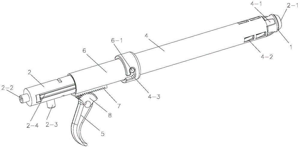
[0035] like Figure 1-8 As shown, a progressive apron launch mechanism includes an inner tube 2 and a sleeve 4, the inner tube 2 is used to load the apron 1, the sleeve 4 is set on the inner tube 2, and the sleeve 4 is stressed relative to the inner When the tube 2 moves or the inner tube 2 is forced to move relative to the casing 4, the apron 1 is forced to translate outward on the inner tube 2 .

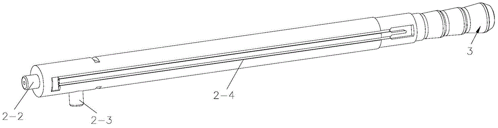
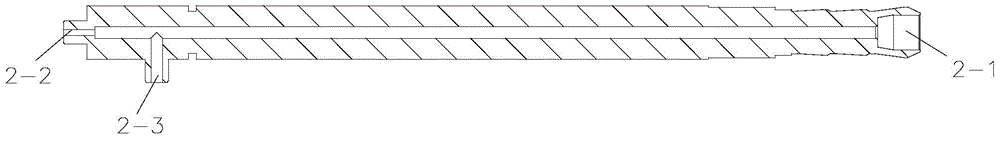
[0036] The front end of the inner tube 2 has three installation parts 3 for installing the rubber ring 1, and a transition section 9 is provided between each installation part 3, and the installation parts 3 are connected through the transition section 9, and three rubber rings are installed on the installation part 3 1. The mounting part 3 includes a rear cone section 3-1, a cylinder section 3-2 and a front cone section 3-3. The large end of the rear cone section 3-1 is connected to one end of the cylinder section 3-2, and the cylinder section 3-2 The other end of the front cone ...

Embodiment 2

[0044] see Figure 9-11 , the difference between embodiment 2 and embodiment 1 is that: the front end of the inner tube 2 has a mounting part 3 for mounting the rubber ring 1, and 2 rib groups are arranged on the mounting part 3, and the rib group consists of 3 ribs 3- 4 are evenly distributed in the circumferential direction, and each rib group is axially arranged side by side on the installation part 3, and the ribs 3-4 of the adjacent rib group are staggered from each other in the axial direction of the inner tube 2, and each rib group The teeth 4-1 and the tongues 4-2 can be accommodated between the ribs 3-4 of the group, because the teeth 4-1 at the front end of the casing 4 and the tongues 4-2 of the tongue group show a staggered structure, so the ribs The structure of the plate group is also corresponding, and it is also shown as staggered, see Image 6 The casing 4 structure shown.

[0045] There are also differences in the plugging of the outer tube 6 and the casing...


PUM


Abstract

The invention relates to a progressive rubber ring launching mechanism which comprises an inner pipe and a sleeve, wherein the inner pipe is used for loading rubber rings; the sleeve sleeves the inner pipe; when the sleeve is stressed to move relative to the inner pipe or the inner pipe is stressed to move relative to the sleeve, the rubber rings are forced to translate outwards on the inner pipe. In order to realize continuous launching of the rubber rings on a ligation device, the relative movement of the inner pipe and the sleeve is adopted in the scheme, so that translation of the rubber rings is pushed; the rubber ring launching mechanism has an automatic rubber ring substitution function; in a rubber ring ligation process, the other subsequent rubber rings can be positioned on a to-be-ligated station at any time, so that the ligation continuity is realized, the ligation process is quickened, and pains of patients are alleviated.

Description

technical field [0001] The invention relates to the technical field of medical devices, in particular to the application field of a ligation device, especially the emitting part of the rubber ring in the ligation device. Background technique [0002] Hemorrhoids is a chronic disease of one or more soft veins formed by varicose venous plexuses at the bottom of the anorectum and anal mucosa. Nowadays, the medical treatment of hemorrhoids mostly adopts the method of surgical resection, which is expensive. The postoperative wound area is large, and the patient suffers from unbearable pain. In view of this reason, in clinical treatment, hemorrhoid ligation device is used. The tissue under the circle will gradually be necrotic and fall off due to lack of blood circulation, and will eventually be excreted from the body. [0003] Chinese patent 201220254047.7 discloses a hemorrhoid ligation device, which adopts a traction wire to bind each hair rubber ring on the lesion site, speci...

Claims


Application Information

Patent Timeline
Patent Type & Authority Applications(China)
IPC IPC(8): A61B17/12
CPCA61B17/12009
Inventor 高云飞董春华
Owner JIANGSU ATE MEDICAL TECH
Features
  • R&D
  • Intellectual Property
  • Life Sciences
  • Materials
  • Tech Scout
  • Unparalleled Data Quality
  • Higher Quality Content
  • 60% Fewer Hallucinations
Learn More