
Filtering and stirring tank

A stirring tank and stirring shaft technology, which is applied to mixer accessories, mixers with rotating stirring devices, and dissolving directions, can solve the problems that the stirring tank does not have filtration characteristics and reflux characteristics, etc., and achieves wide stirring range, easy operation and practicality. strong effect

Inactive Publication Date: 2015-04-29
DALIAN 858 INNOVATION WORKS TECH SERVICE
View PDF0 Cites 1 Cited by
  • Summary
  • Abstract
  • Description
  • Claims
  • Application Information

AI Technical Summary

Problems solved by technology

[0004] At present, the stirring tank does not have the filtration and reflux characteristics. Sometimes there is still a certain amount of precipitation in the substance that needs to be stirred, which needs to be removed during stirring to prevent damage to the stirring rod. Therefore, it is necessary to provide a new type of stirring tank to solve the above problems.

Method used


Image

  • Filtering and stirring tank

Examples


Embodiment Construction

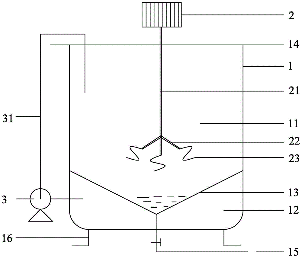
[0016] like figure 1 As shown, a filter stirring tank includes a tank body 1, a motor 2 arranged on the upper end of the tank body 1, and the lower end of the motor 2 is connected with a stirring shaft 21, and the lower end of the stirring shaft is provided with three stirring rods with variable angles. 22. The bottom of the tank body 1 is provided with at least two bases 16, and the interior of the tank body 1 is divided into a stirring zone 11 and a filtering zone 12 by a conical filter screen 13 arranged at the lower end of the tank body 1. The lowest part of the net 13 is communicated with a sewage pipe 15 with a valve, and the upper end of the tank body 1 is provided with a cover 14 to prevent liquid from splashing.

[0017] The lower end of the stirring rod 22 is provided with a helical stirring blade 23 .

[0018] The side wall of the filter area 12 of the tank body 1 is provided with an output pipeline connected with the pump 3, and the pump 3 returns the liquid extra...


PUM


Abstract

The invention discloses a filtering and stirring tank comprising a tank body and a motor arranged at the upper end of the tank body, wherein the lower end of the motor is connected with a stirring shaft; the lower end of the stirring shaft is provided with three angle-changeable stirring rods; and the bottom of the tank body is provided with at least two bases. The filtering and stirring tank is characterized in that the inside of the tank body is divided into a stirring region and a filtering region by a tapered filter screen arranged at the lower end of the tank body; the lowest part of the filter screen is communicated with a drain pipe with a valve; and the upper end of the tank body is provided with a cover for preventing a liquid from being splashed. The filtering and stirring tank has the advantages of simple structure, strong practicability, convenience in operation, favorable filtering effect and the like.

Description

technical field [0001] The invention relates to the field of stirring devices, in particular to a filter stirring tank. Background technique [0002] Mixing tanks can also be called water phase tanks, which are widely used in coatings, medicine, building materials, chemicals, pigments, resins, food, scientific research and other industries. The equipment can be made of carbon steel, stainless steel and other materials according to the process requirements of the user's products, and can be equipped with heating and cooling devices to meet different process and production needs. Heating forms include jacket electric heating and coil heating. The equipment has reasonable structural design, advanced technology, durability, simple operation, and convenient use. It is an ideal chemical equipment with low investment, fast commissioning, and high returns. [0003] The mixing tank can realize feeding control, discharging control, stirring control and other manual and automatic cont...

Claims


Application Information

Patent Timeline
IPC IPC(8): B01F7/24B01F15/02
Inventor 秦宏佳
Owner DALIAN 858 INNOVATION WORKS TECH SERVICE
Learn More