
Novel dual-transmission combined efficient sorting machine

A dual-drive, combined technology, applied in centrifuges and other directions, can solve the problems of low cleaning rate, high system energy consumption, and increase production costs, and achieve the effects of reducing production costs, improving powder selection efficiency, and reducing steel consumption.

Inactive Publication Date: 2015-04-29
MIANYANG LANAO HEAVY MACHINERY MFG
View PDF13 Cites 2 Cited by
  • Summary
  • Abstract
  • Description
  • Claims
  • Application Information

AI Technical Summary

Problems solved by technology

[0002] In the processing of split materials in the fields of building materials, metallurgy, and chemical industry, the bulk materials are often ground and sorted by a powder separator, and then the fine powder that meets the material standards is processed into finished products, which do not meet the requirements. The standard coarse material is sorted by re-grinding, but after the existing powder classifier spreads the material through the spreading plate, the material enters the powder selection chamber for only one sorting, which leads to incomplete separation of coarse powder and a large amount of Fine powder and coarse powder are mixed together into the lower cone, and returned to the grinder for re-grinding. Mixing fine powder and coarse powder into the grinder for grinding will intensify the repeated work of the grinder and increase the loss of steel balls in the grinder. And because the pulverizer is a kind of high energy consumption equipment, it will increase the production cost accordingly, and at the same time, it will also lead to low powder selection efficiency of the powder separator. The low selection rate is generally about 55%, low output and high energy consumption of the system

Method used


Image

  • Novel dual-transmission combined efficient sorting machine

Examples


Embodiment 1

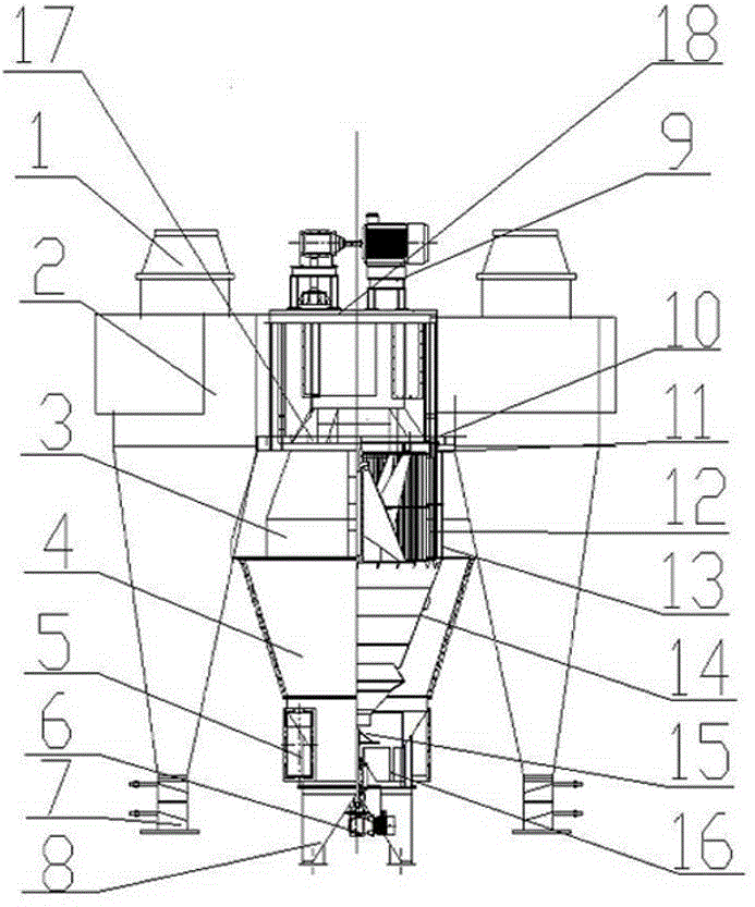
[0020] A new double-drive combined high-efficiency separator, such as figure 1 As shown, it includes feed inlet 17, finished product collector 2, upper powder selection chamber 3, middle powder selection chamber 4, material spreading plate 10, baffle plate 11, upper rotor 12, guide vanes 13, middle cone 14, lower Powder selection chamber 16, main support 18; the main support 18 runs through and fixes the upper powder selection chamber 3, the middle powder selection chamber 4 and the lower powder selection chamber 16, the upper powder selection chamber 3 is connected with the middle powder selection chamber 4, and the middle powder selection chamber The chamber 4 is connected with the lower powder selection chamber 16, the upper end of the upper powder selection chamber 3 is connected with the feed port 17, the two sides or surroundings of the upper powder selection chamber 3 are connected with the finished product collector 2, and the upper powder selection chamber 3 is provide...

Embodiment 2

[0025] This embodiment is further optimized on the basis of the above-mentioned embodiments, the lower end of the finished product collector 2 is provided with a finished product discharge port 7, the upper end of the described finished product collector 2 is provided with an air outlet 1, and the finished product discharge port 7 The setting is mainly convenient for operators to collect finely ground finished products from the lower end of the finished product collector 2, and the number of finished product collectors 2 is consistent with the number of discharge ports. Other structures involved in this embodiment are the same as those in the foregoing embodiment, and will not be repeated here.

Embodiment 3

[0027]This embodiment is further optimized on the basis of the above-mentioned embodiments. The structure of the new double-transmission combined high-efficiency separator also includes an upper transmission device 9, and the upper transmission device 9 is arranged on the upper end of the main support 18, and the main shaft and the upper The rotor 12 is connected. The upper transmission device 9 mainly provides power, and realizes the work of driving the upper rotor 12 through the main shaft. The high-speed rotation of the upper rotor 12 forms a horizontal vortex under the action of the guide vane 13, and the material is selected under the horizontal vortex area formed and its own gravity. , grading, wherein the upper transmission device 9 passes through the main shaft and the upper rotor 12, which is not a conventional technical means in the field. Other structures involved in this embodiment are the same as those in the foregoing embodiment, and will not be repeated here.


PUM


Abstract

The invention discloses a novel dual-transmission combined efficient sorting machine. The machine comprises a feeding port, a finished product collector, an upper powder selection chamber and a main support. The main support penetrates and fixes the upper powder selection chamber, a middle powder selection chamber and a lower powder selection chamber. The upper powder selection chamber is connected with the middle powder selection chamber which is connected with the upper powder selection chamber. The upper end of the upper powder selection chamber is connected with the feeding port, and two sides or the periphery of the upper powder selection chamber are or is connected with the finished product collector. A guide blade and an upper rotor are arranged in the upper powder selection chamber, and the upper rotor is disposed on the inside of the guide blade. A scattering plate is arranged above the retaining plate which is arranged above the upper rotor and the guide blade. A middle tapered element is arranged in the middle powder selection chamber, and the upper end of the middle tapered element is connected with the upper powder selection chamber. A coarse powder returning port is formed in the lower end of the lower powder selection chamber, and a lower rotor is arranged in the lower powder selection chamber. By means of the machine, the efficiency and the yield of grinding equipment are improved, and steel consumption and power consumption of the grinding equipment are reduced.

Description

technical field [0001] The invention relates to the field of separation of building materials, metallurgy, and chemical powder materials, in particular to a novel dual-drive combined high-efficiency separator. Background technique [0002] In the processing of split materials in the fields of building materials, metallurgy, and chemical industry, the bulk materials are often ground and sorted by a powder separator, and then the fine powder that meets the material standards is processed into finished products, which do not meet the requirements. The standard coarse material is sorted by re-grinding, but after the existing powder classifier spreads the material through the spreading plate, the material enters the powder selection chamber for only one sorting, which leads to incomplete separation of coarse powder and a large amount of Fine powder and coarse powder are mixed together into the lower cone, and returned to the grinder for re-grinding. Mixing fine powder and coarse ...

Claims


Application Information

Patent Timeline
Patent Type & Authority Applications(China)
IPC IPC(8): B04B5/10B04B9/08B04B7/00
Inventor 王建军
Owner MIANYANG LANAO HEAVY MACHINERY MFG
Learn More