Powder concentrator

A powder separator and cylinder technology, which is applied in the direction of solid separation, separation of solids from solids with airflow, grain processing, etc., can solve the problems of low efficiency of powder selection and poor dispersion efficiency, etc.

Active Publication Date: 2020-10-23
陕西正元粉煤灰综合利用有限公司
View PDF6 Cites 1 Cited by
  • Summary
  • Abstract
  • Description
  • Claims
  • Application Information

AI Technical Summary

Problems solved by technology

[0004] In view of the above-mentioned related technologies, the inventor believes that the existing powder classifier can only disperse the

Method used


Image

  • Powder concentrator
  • Powder concentrator
  • Powder concentrator

Examples


Embodiment Construction

[0036] The following is attached Figure 1-6 The application is described in further detail.

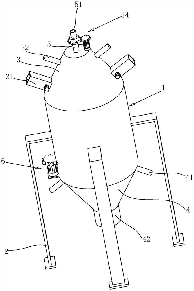
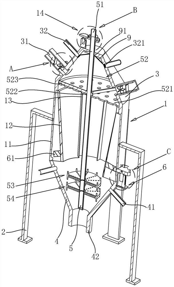
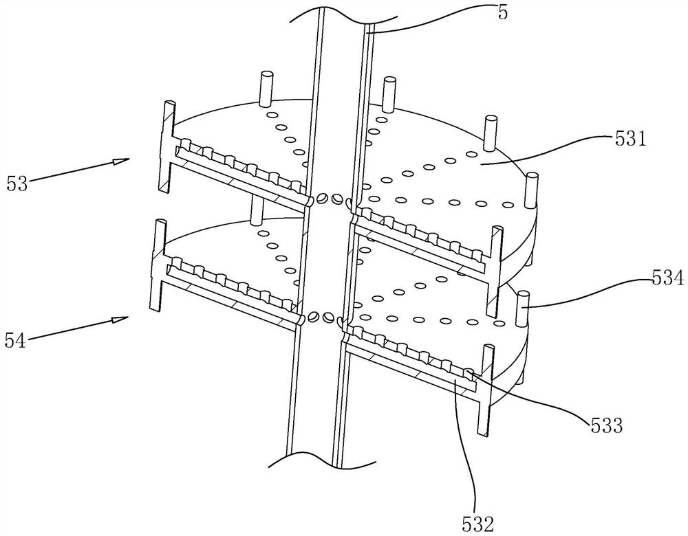
[0037] The embodiment of the present application discloses a powder separator. Such as figure 1 , figure 2 As shown, the powder classifier includes a cylinder body 1 and a bracket 2 fixed on the outside of the cylinder body 1. The top of the cylinder body 1 is fixed with a truncated upper shell 3, and the bottom of the cylinder body 1 is fixed with a funnel-shaped lower shell 4. The side wall of the shell 3 is provided with a feed pipe 31 near the side of the cylinder body 1, the side wall of the upper shell 3 is located above the feed pipe 31 and is provided with a discharge pipe 32, the side wall of the lower shell 4 is provided with an air inlet pipe 41, and the bottom of the lower shell 4 Coarse material outlet 42 is provided, the top center of upper shell 3 rotates vertically and is provided with a rotating tube 5 closed at the bottom, and the rotating tube 5 extends into th...


PUM


Abstract

The invention relates to a powder concentrator. The powder concentrator comprises a cylinder and a bracket, wherein an upper shell is arranged at the top of the cylinder; a lower shell is arranged atthe bottom of the cylinder; the cylinder comprises a fixed shell, a centrifugal cylinder and a material plate; a first driving piece for driving the centrifugal cylinder to rotate is arranged at the external part of the centrifugal cylinder; a feed pipe and a discharge pipe are arranged on the side wall of the upper shell; an intake pipe and a coarse material outlet are arranged on the side wall of the lower shell; a rotating pipe with a closed bottom is vertically and rotationally inserted in the top center of the upper shell; the rotating pipe extends into the lower shell; the rotating pipeis rotationally sleeved with a ventilation pipe out of the upper shell; a second driving device for driving the rotating pipe to rotate is arranged at the top of the upper shell; a scattering device is arranged at the external part of the rotating pipe above the centrifugal cylinder; a first air blowing scattering device is arranged at the external part of the rotating pipe below the centrifugal cylinder and communicating with the rotating pipe; and a second air blowing scattering device is arranged below the first air blowing scattering device and communicating with the rotating pipe. The powder concentrator is simple in structure, improves the powder scattering efficiency, and improves the powder concentration efficiency.

Description

technical field [0001] The present application relates to the field of powder sorting equipment, in particular to a powder sorter. Background technique [0002] At present, the powder classifier is widely used in the construction and metallurgical industries because of its functions of breaking up materials, drying and grading. Most of the existing dry powder separators are dynamic powder separators, including centrifugal, cyclone, rotor and other types. A common feature of these types of powder separators is that they use wind to blow materials from bottom to top. When it is blown to the grading rotor or the small fan blade which acts as a fence, the coarser material will fall into the coarse powder area due to the action of gravity, centrifugal force, etc., and the downward force is greater than the upward force, while the fine powder will continue to go up. Enter the fine powder area, so as to realize the classification of powder. [0003] The Chinese invention with the...

Claims


Application Information

Patent Timeline
IPC IPC(8): B02C19/00B02C23/14B02C23/16B02C23/30B02C23/32B07B7/01
CPCB02C19/00B02C23/14B02C23/16B02C23/30B02C23/32B02C2023/165B07B7/01
Inventor 任思谦马全章王巍
Owner 陕西正元粉煤灰综合利用有限公司
Why Eureka
Try Eureka