Supporting hinged shaft forging technology

A technology of technology and hinge shaft, which is applied in the field of forging technology, can solve the problems of short service life, large amount of material waste, material waste, etc., and achieve the effect of improving service life, reducing processing amount, and simple process

Inactive Publication Date: 2015-04-29
CHONGQING YANLIAN HEAVY MACHINERY EQUIP
View PDF3 Cites 5 Cited by
  • Summary
  • Abstract
  • Description
  • Claims
  • Application Information

AI Technical Summary

Problems solved by technology

Although the product can be formed in this way, there are following deficiencies in such a process: 1. The processing amount is large, resulting in long processing time; 2. When turning on a lathe, the amount of material waste is larg...

Method used


Image

  • Supporting hinged shaft forging technology

Examples


Embodiment 1

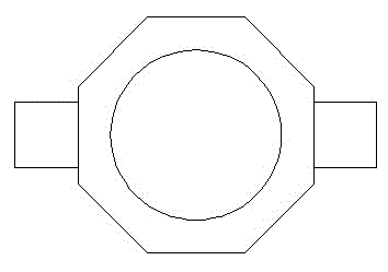
[0013] Embodiment 1: as figure 1 As shown, a supporting hinge shaft forging process, the process includes the following steps: (1) chamfering one end of the steel ingot blank, pressing the other end to the riser to make a clamp, cutting off the excess length, cutting the nozzle, and deburring; (2) Put the blank into the leaking plate and upset to the design size; (3) Take out the blank and press the square chamfer, pull out the eight sides to round to the design size, and tweezer; (4) Pull out the rod, forge the steps at both ends to the design size, and then Put the two ends into the mold and upset to the design size; (5) Flatten the two ends to the design size, repeatedly close all directions, and punch holes on both sides with a punch; (6) Use the horse rod to ream the hole twice to reach the design size; (7) Flatten both ends so that the thickness reaches the design size, then fill the inner hole with a punch, and finally level it; (8) After the red measurement size is qua...


PUM


Abstract

The invention discloses a supporting hinged shaft forging technology. The supporting hinged shaft forging technology includes following steps: (1) chamfering one end of a steel ingot blank, pressing a dead head at the other end of the steel ingot blank so as to form a pincer handle, cutting an unnecessary segment of the steel ingot blank, cutting a water gap, and removing burrs; (2) placing the steel ingot blank into a hole disk, and performing upsetting on the steel ingot blank; (3) fetching out the steel ingot blank, chamfering four edges of the steel ingot blank, rounding the steel ingot blank from all directions, and filing the pincer handle; (4) drawing the steel ingot blank into a pole, forging the pole until steps at two ends of the pole are forged to the designed dimension, and then placing the two ends of the pole into a die, and performing upsetting on the pole; (5) smoothing the two ends of the pole, repeatedly shrinking the pole in all the directions, and using a punch to push double sides of the pole; (6) using a martensite rod to perform chambering twice; (7) smoothing two end faces of the pole, enabling the thickness of the two end faces of the pole to reach the designed size, and inserting the punch into a round inner hole so as to smooth the round inner hole; (8) performing heat treatment after the size of the pole is qualified through measurement. The supporting hinged shaft forging technology has the advantages of being simple and convenient, can be used to directly obtain a qualified product through a forging method, prevents lathing from damaging tissue fibers of the product, prolongs use life of the product, and simultaneously reduces a processing volume, saves materials, and reduces cost.

Description

technical field [0001] The invention relates to a forging process, in particular to a support hinge shaft forging process. Background technique [0002] The main steps of the existing supporting hinge shaft forging process are: first forging the rough material into an octagonal forging, and then putting it into a lathe to cut and shape the bearing installation position. Although the product can be formed in this way, there are following deficiencies in such a process: 1. The processing amount is large, resulting in long processing time; 2. When turning on a lathe, the amount of material waste is large, which wastes materials and improves the processing efficiency. 3. During the turning process, the fibrous structure of the forging is destroyed, which affects the quality of the forging, resulting in a shorter service life of the product. Contents of the invention [0003] The object of the present invention is to provide a support hinge shaft forging process capable of...

Claims


Application Information

Patent Timeline
IPC IPC(8): B21J5/06B21J1/06
Inventor 刘正邹洪梅张光华
Owner CHONGQING YANLIAN HEAVY MACHINERY EQUIP
Why Eureka
Try Eureka