Molds for turbines of automotive turbochargers

A turbocharger and turbine technology, which is applied in the field of turbine molds, can solve the problems that the mold is difficult to guarantee the molding size and quality, the space for weight removal is limited, and the working conditions are harsh, so as to ensure the size, facilitate modification and processing, and improve molding quality effect

Active Publication Date: 2016-09-28
JIANGSU WANLI MACHINERY
View PDF6 Cites 0 Cited by
  • Summary
  • Abstract
  • Description
  • Claims
  • Application Information

AI Technical Summary

Problems solved by technology

[0004] The turbine works at high temperature, and the working conditions are relatively harsh. Since it is a high-speed rotating part, it must be carefully balanced before assembly. Due to the continuous increase in engine power density, the required turbocharger speed is also corresponding The higher the speed of the turbocharger, the higher the requirements for the dynamic balance accuracy of the turbine. The blades, hub and cover of the turbine adopt an integrated structure, and the space on the turbine for dynamic balance and weight removal is limited. It is required to continuously improve the quality of the turbine and reduce the initial unbalance of the turbine as much as possible. As can be seen from the figure, the turbine has a high-precision complex surface, and it is difficult for ordinary molds to guarantee its molding size and quality.

Method used


Image

  • Molds for turbines of automotive turbochargers
  • Molds for turbines of automotive turbochargers
  • Molds for turbines of automotive turbochargers

Examples


Embodiment Construction

[0033] The present invention is further described in conjunction with the following examples.

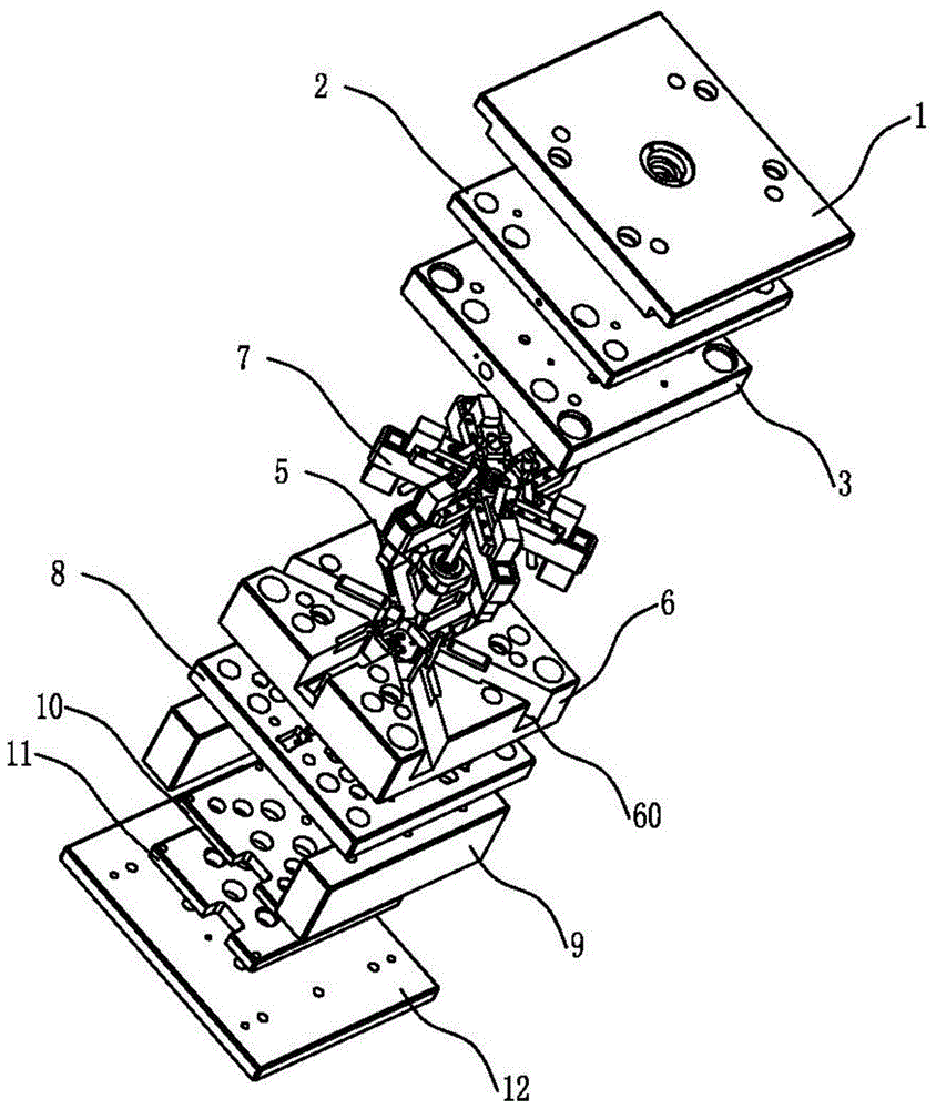
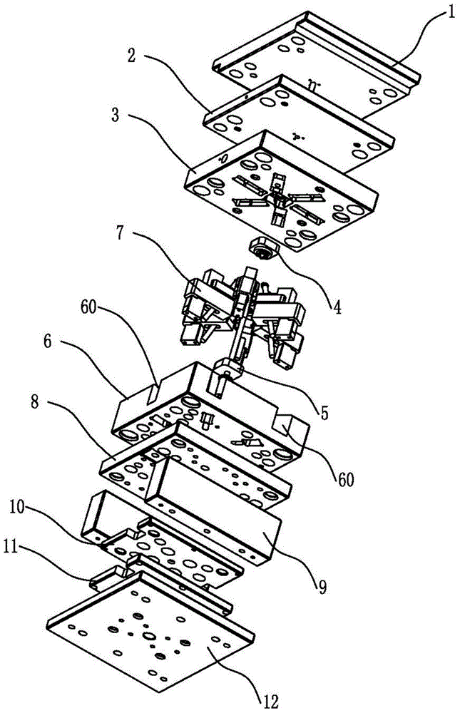
[0034] The mold that the present invention creates is used for the turbine of automobile turbocharger, as figure 1 with figure 2 As shown, it includes fixed mold bottom plate 1, stripper plate 2, fixed template 3, fixed mold core 4, row assembly 7, movable mold core 5, movable template 6, movable mold backing plate 8, square iron 9 and The movable die bottom plate 12 is a face needle plate 10 and a bottom needle plate 11 arranged in sequence between the two square irons 9 . The fixed mold core 4 is arranged in the mold cavity of the fixed template 3 , and the movable mold core 5 is arranged in the mold cavity of the movable template 6 . The main channel extending downward from the fixed mold bottom plate 3 is divided into three secondary runners extending to the fixed mold core 4 at the fixed mold plate 3, and the three secondary runners are evenly distributed around the axis of ...


PUM


Abstract

The invention relates to the technical field of molds and particularly relates to a mold for a worm wheel of an automobile worm wheel supercharger. The mold comprises a fixed mold bottom plate, a stripping plate, a fixed mold plate, a fixed mold core, line assemblies, a movable mold core, a movable mold plate, a movable mold base plate, square iron, a top needle plate, a bottom needle plate and a movable mold bottom plate, wherein the line assemblies are arranged at the peripheries of the mold cores; each line assembly comprises a line push seat, a line slide seat, a line upper insert, a line lower insert, line guide blocks, a line stopping block and an inclined guide column; each line push seat is mounted on the movable mold base plate and the upper part of the line push seat is inserted into the corresponding line slide seat; each line slide seat is provided with an inclined groove; each line lower insert is embedded into the corresponding inclined groove from the front end of each line slide seat; each line upper insert is embedded into the top surface of the corresponding line lower insert from the rear end of the corresponding line lower insert; the line guide blocks are fixedly arranged on the two sides of a corresponding slide groove; the line stopping blocks are stopped and pressed at the rear ends of the corresponding line inserts; and the inclined guide columns obliquely penetrate through the movable mold base plate from the fixed mold plate. The mold is used for forming the high-precision and high-quality worm wheel, and the dynamic balance precision of the worm wheel is improved.

Description

technical field [0001] The invention relates to the technical field of moulds, in particular to a mould for a turbine of an automobile turbocharger. Background technique [0002] The turbocharger is an important part of a modern engine. Under the influence of environmental protection, energy crisis and other factors, the application of the turbocharger has developed rapidly. The turbocharger is a key part of the turbocharger. It The function is to absorb the exhaust energy of the engine, convert heat energy and pressure energy into mechanical work, drive the coaxial compressor impeller to rotate at high speed, absorb fresh air from the atmosphere, pressurize it and press it into the engine cylinder, so as to increase engine power and save energy. oil and to improve discharge purposes. [0003] figure 1 Shown is the structure of the turbine, including the hub, blades and cover. The hub in the middle is connected to the rotating shaft. A plurality of blades are evenly distri...

Claims


Application Information

Patent Timeline
Patent Type & Authority Patents(China)
IPC IPC(8): B22C9/02B22C9/28B22C9/08
CPCB22C9/02B22C9/082B22C9/22
Inventor 殷文元谢善忠吴铭杰陈歆
Owner JIANGSU WANLI MACHINERY
Why Eureka
Try Eureka