An electric spindle design adopting air static pressure anti-thrusting and electromagnetism radical bearing support

A technology of radial bearings and electric spindles, applied in the field of machinery, can solve the problems that electric spindles cannot be lubricated by oil mist or oil and air, the structural strength and conductivity of aluminum alloy strips are low, and the structure of PCB electric spindles cannot be applied, etc., to achieve overall The effect of compact structure, simple structure, and easy concentration of gas supply pipelines

Active Publication Date: 2009-11-18
LUOYANG BEARING RES INST CO LTD
View PDF4 Cites 0 Cited by
  • Summary
  • Abstract
  • Description
  • Claims
  • Application Information

AI Technical Summary

Problems solved by technology

[0002] In the PCB plate drilling processing industry, because the drilling diameter is getting smaller and smaller, the production efficiency requirements are getting higher and higher. Therefore, in order to meet this need, the speed requirements of the electric spindle for PCB drilling are also getting higher and higher, and Ordinary PCB electric spindle structure is no longer suitable for ultra-high speed, especially the support of the electric spindle shaft system no longer matches the ultra-high-speed motor system, because:
[0003] 1. Because the DmN value of the bearing is too high, and the industry requires that the electric spindle cannot be lubricated by oil mist or oil and air, the traditional rolling element bearing cannot be applied;
[0004] 2. The rotor of the traditional electric spindle motor adopts the structure of cast aluminum with magnetic steel sheet. Because the linear speed of the rotor surface is too high, and the structural strength and conductivity of the aluminum alloy strip are low, it is easy to cause the rotor to creep under the ultra-high speed state, causing the electric spindle The vibration of the shaft system is too large, which affects the processing quality of the spindle

Method used


Image

  • An electric spindle design adopting air static pressure anti-thrusting and electromagnetism radical bearing support

Examples


Embodiment Construction

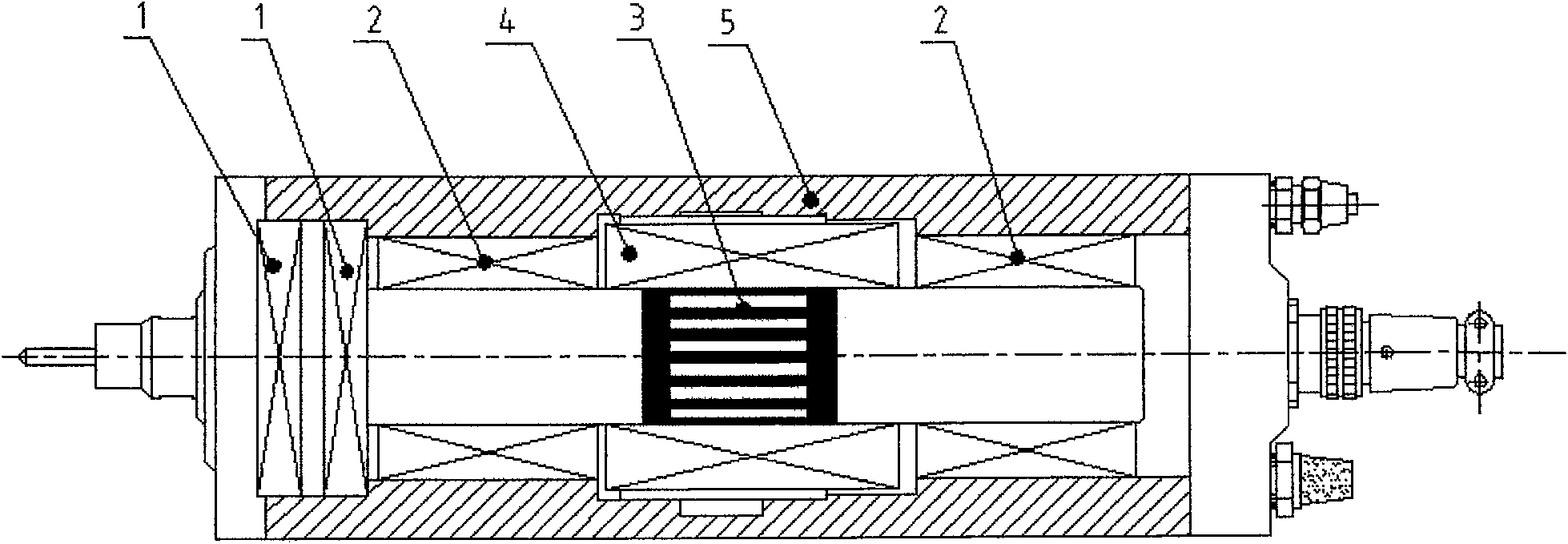
[0015] Such as figure 1 As shown, in the electric spindle supported by aerostatic thrust and electromagnetic radial bearings of the present invention, two The centralized configuration of the aerostatic pressure thrust bearing (1) can optimize the use of the space inside the electric spindle housing (5), making the overall structure of the electric spindle compact, and at the same time, the air supply pipeline of the aerostatic pressure bearing (1) is convenient Centralized, it is convenient for the installation of the electric spindle, and provides the required axial rigidity for the rotor-shaft integrated shaft system (3); the stator (4) installed in the electric spindle housing (5) is symmetrically arranged on both sides with electromagnetic radial The bearing (2) is used to support the rotor-rotating shaft integrated shafting (3). The symmetrically arranged electromagnetic radial bearings (2) can reduce the load of the rotor-rotating shaft integrated shafting (3) when the ...


PUM


Abstract

An electric spindle supported by aerostatic pressure thrust and electromagnetic radial bearings. According to the external dimension limitation and rigidity requirements of the electric spindle, two airstatic pressure stoppers are centrally arranged in the end of the electric spindle housing (5) close to the output end. The push bearing (1) optimizes space utilization and compact structure, and at the same time facilitates the concentration and installation of air supply pipelines, and provides the required axial stiffness for the rotor-rotating shaft integrated shafting (3); when installing the stator (4) Electromagnetic radial bearings (2) are symmetrically arranged on both sides to support the integrated rotor-rotating shaft shafting system, reduce the vibration of the shafting system (3) and ensure its radial stiffness; The bar and the rotating shaft are made as an integral structure, and the position corresponding to the stator installed in the electric spindle shell, that is, the squirrel cage bar is directly welded in the groove with copper alloy to reduce the creep deformation of the squirrel cage bar and reduce vibration. Improve electrical conductivity and structural strength.

Description

technical field [0001] The invention belongs to the technical field of machinery, and in particular relates to an electric main shaft adopting aerostatic pressure thrust and electromagnetic radial bearing support. Background technique [0002] In the PCB plate drilling processing industry, because the drilling diameter is getting smaller and smaller, the production efficiency requirements are getting higher and higher. Therefore, in order to meet this need, the speed requirements of the electric spindle for PCB drilling are also getting higher and higher, and Ordinary PCB electric spindle structure is no longer suitable for ultra-high speed, especially the support of the electric spindle shaft system no longer matches the ultra-high-speed motor system, because: [0003] 1. Because the DmN value of the bearing is too high, and the industry requires that the electric spindle cannot be lubricated by oil mist or oil and air, the traditional rolling element bearing cannot be used...

Claims


Application Information

Patent Timeline
Patent Type & Authority Patents(China)
IPC IPC(8): H02K7/08H02K7/09H02K5/16F16C32/06F16C32/04
Inventor 陈长江徐同申邱宪国肖汝峰傅广森郭丽娟田民黄昆俞蓬
Owner LUOYANG BEARING RES INST CO LTD
Why Eureka
Try Eureka