Supercharge Your Innovation With Domain-Expert AI Agents!

Loop knife back pushing device for rubber slicer

A rubber sheet and knife device technology, applied in metal processing and other directions, can solve the problems of easy to wear knife back, reduce the life of the belt knife, etc., and achieve the effect of solving the problem of retracting the knife, reducing wear and improving life.

Active Publication Date: 2015-04-29
TAIXING SHUANGYANG LEATHER RUBBER MACHINERY FACTORY
View PDF5 Cites 1 Cited by
  • Summary
  • Abstract
  • Description
  • Claims
  • Application Information

AI Technical Summary

Problems solved by technology

The disadvantage of this technical solution is that the continuous friction between the back of the knife and the limit block will generate huge heat and easily wear the back of the knife, reducing the life of the belt knife

Method used


Image

  • Loop knife back pushing device for rubber slicer

Examples


Embodiment Construction

[0012] The specific embodiment of the present invention is described in further detail below in conjunction with accompanying drawing:

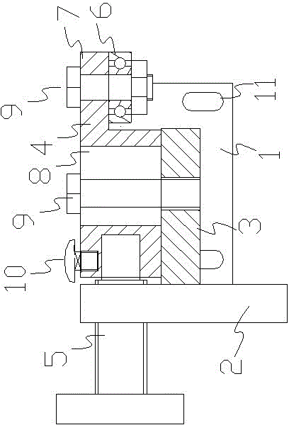
[0013] A rubber sheet cutting machine with a knife back pushing knife device, including a mounting seat, the mounting seat includes a mounting plate 1, a support seat 2 and a horizontal seat 3, the mounting plate is provided with bolt holes 11, the horizontal seat 3 is vertically connected with the support base 2, the horizontal base 3 and the support base 2 are both fixedly connected to the mounting plate 1, the feed block 4 is installed on the horizontal base, and the feed block 4 is provided with a Waist-shaped slot 8, the horizontal seat 3 is provided with a bolt hole corresponding to the waist-shaped slot 8, and the feed block 4 and the horizontal seat 3 are adjustable connected by bolts. One end of the feed block 4 close to the support base 2 is provided with a threaded hole, and the threaded hole is screwed with the end o...


PUM


Abstract

The invention relates to a loop knife back pushing device for rubber slicer. The loop knife back pushing device for rubber slicer comprises a mounting seat; the mounting seat comprises a mounting plate, a support seat and a horizontal seat, wherein the mounting plate is provided with bolt holes, the horizontal seat is perpendicularly connected with the support seat, and the horizontal seat and the support seat are fixedly connected to the mounting plate; a feeding block is mounted on the horizontal seat, and one end of the feeding block, which is close to a knife back, is provided with a bearing; the axis of the bearing is perpendicular to a knife loop plane, and the bearing is in contact with the knife back. Through rolling friction between the knife back and the bearing, the problem of knife retraction can be effectively solved, meanwhile, wearing of the knife back can be reduced and the service life of a loop knife can be prolonged.

Description

technical field [0001] The invention relates to a rubber sheet cutting machine, in particular to a knife-back pushing device with a knife for the rubber sheet cutting machine. Background technique [0002] The circular band knife of the rubber sheet cutting machine cuts rubber. During the cutting process, due to the elasticity and resistance of the rubber and the soft special effect of the band knife, the knife will retreat, and the knife will bend or the knife will retreat toward the back of the knife. Bring inconvenience to the cutting of rubber. The solution in the prior art is: use tungsten steel or alloy steel to support the limit block at the back of the knife to prevent the knife from withdrawing. The defect of this technical solution is that the continuous friction between the back of the knife and the limit block will generate huge heat and easily wear the back of the knife, reducing the life of the belt knife. Contents of the invention [0003] ...

Claims


Application Information

Patent Timeline
IPC IPC(8): B26D7/08B26D1/46
CPCB26D1/46B26D7/08
Inventor 尹家旺
Owner TAIXING SHUANGYANG LEATHER RUBBER MACHINERY FACTORY
Features
  • R&D
  • Intellectual Property
  • Life Sciences
  • Materials
  • Tech Scout
  • Unparalleled Data Quality
  • Higher Quality Content
  • 60% Fewer Hallucinations
Learn More