
Storage forklift acceleration device

A technology for acceleration devices and forklifts, applied in the layout of power plant control mechanisms, electric vehicles, vehicle components, etc., can solve the problems of mechanical errors of the transmission mechanism, decreased precision, and vehicle out-of-control, to avoid mechanical errors, stable operation, and effective reliable results

Active Publication Date: 2017-04-05
杭州联核科技有限公司
View PDF4 Cites 0 Cited by
  • Summary
  • Abstract
  • Description
  • Claims
  • Application Information

AI Technical Summary

Problems solved by technology

The principle is simple, but after the potentiometer is subjected to long-term sliding friction and the resistor body is worn out, the accuracy will decrease, or even fail completely, which will cause the vehicle to lose control
[0003] Another situation is mechanical control, which uses gear transmission, but there is also a problem with this structure. After a long time of use, the transmission mechanism will cause mechanical errors due to mechanical looseness caused by wear and tear.

Method used

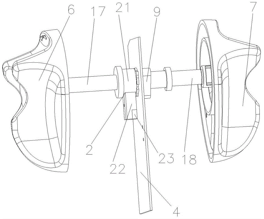
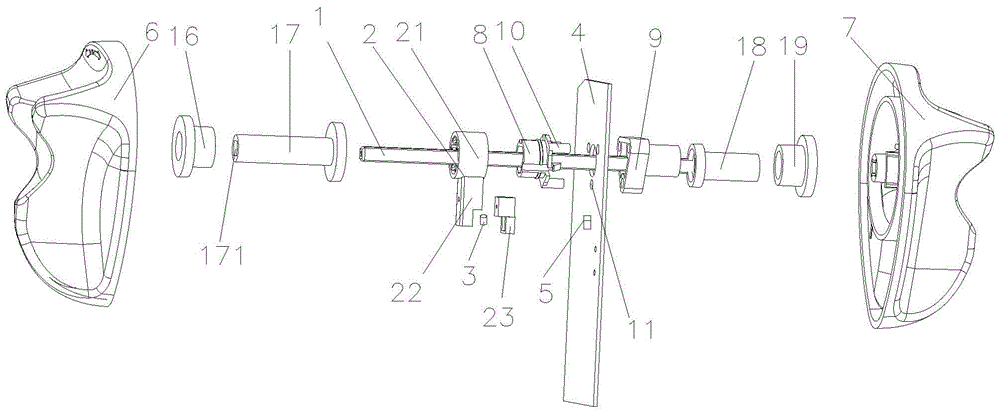

Image

  • Storage forklift acceleration device
  • Storage forklift acceleration device
  • Storage forklift acceleration device

Examples


Embodiment 1

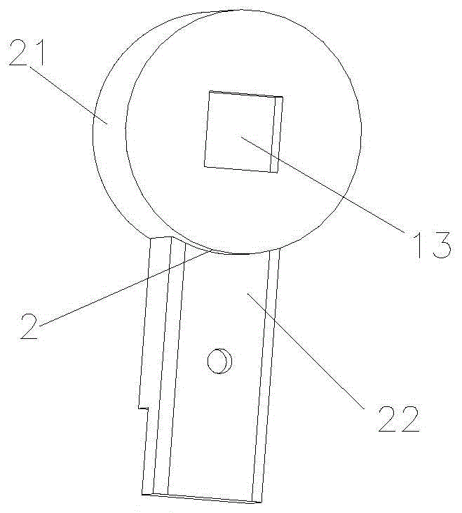
[0038] Embodiment 1: as image 3 , the section of the knob shaft 1 is rectangular, and the side of the connecting portion 21 away from the fixed block one 8 is provided with a first rectangular through hole 13 matching the outer surface of the knob shaft 1 .

Embodiment 2

[0039] Embodiment 2: as Figure 4 The side of the connection part 21 far away from the fixed block 8 is a hollow semi-closed structure, and the center of the side of the connection part 21 away from the fixed block 8 is provided with a second rectangular through hole 14 matching the outer surface of the knob shaft 1. Between the four vertices of the two rectangular through holes 14 and the inner wall of the connecting part 21, there is an S-shaped connecting bracket 15 lying along one direction. The bracket helps to offset part of the tension generated by the rotation, effectively preventing the junction of the connecting bracket and the connecting part, the junction of the connecting bracket and the outer frame of the second rectangular through hole, and the possibility of fracture and damage of the connecting bracket, which greatly improves stable effect, at the same time, the protection scope of the present invention is not limited to the two cases of embodiment 1 and embod...


PUM


Abstract

The invention relates to a warehousing forklift accelerator, which comprises a rotating handle, a rotary knob rotating shaft, a rotating block, a steel magnet and a PCB (Printed Circuit Board) control circuit board, wherein the rotating handle is arranged at the ends of the rotary knob rotating shaft, the rotating block is fixedly connected with the rotary knob rotating shaft, the steel magnet is arranged at the end of the rotating block, the PCB control circuit board sleeves the rotary knob rotating shaft, a magnet position sensor and a controller are arranged on the PCB control circuit board, the magnet position sensor is connected with the input end of the controller, and the steel magnet is arranged corresponding to the magnet position sensor. The structure of the warehousing forklift accelerator disclosed by the invention is simple, the sensor and a detected object are of a non-contact structure, and thereby failure which is caused by the long-time friction between the sensor and the detected object is prevented; because the warehousing forklift accelerator is provided with a non-gear transmission mechanism, mechanical errors which are caused by mechanical looseness as the result of the abrasion of the transmission mechanism are prevented.

Description

technical field [0001] The invention relates to an acceleration device, in particular to an acceleration device for a storage forklift. Background technique [0002] The existing storage forklift handle acceleration sensor, such as a contact potentiometer, calculates the corresponding movement of the rotating shaft by detecting the voltage change in the circuit caused by the sliding of the potentiometer connected to the rotating shaft. The principle is simple, but after the potentiometer is subjected to long-term sliding friction and the resistor body is worn out, the accuracy will decrease, or even fail completely, which will cause the vehicle to lose control. [0003] Another situation is mechanical control, using gear transmission, but there is also a problem with this structure. After a long time of use, the transmission mechanism will cause mechanical errors due to mechanical loosening caused by wear and tear. Contents of the invention [0004] The technical problem ...

Claims


Application Information

Patent Timeline
Patent Type & Authority Patents(China)
IPC IPC(8): B60L15/20B60K26/02
CPCY02T10/72
Inventor 徐昺
Owner 杭州联核科技有限公司
Learn More