Supercharge Your Innovation With Domain-Expert AI Agents!

Device and method for improving deep denitrification of internal carbon source denitrification by improving uct staged water inflow process

A segmented water inflow and deep denitrification technology, applied in chemical instruments and methods, multi-stage water treatment, aerobic and anaerobic process treatment, etc., can solve the problem of increasing the burden of sewage treatment costs, low levels of organic carbon sources, and environmental safety Threats and other issues, to achieve the effect of improving sludge settling performance, increasing total nitrogen removal rate, and reducing total emissions

Active Publication Date: 2016-08-24
BEIJING UNIV OF TECH
View PDF6 Cites 0 Cited by
  • Summary
  • Abstract
  • Description
  • Claims
  • Application Information

AI Technical Summary

Problems solved by technology

[0003] However, in recent years, due to the widespread installation of septic tanks and long drainage pipe networks in my country, the level of organic carbon sources in urban sewage is low, which cannot meet the needs of traditional biological nitrogen and phosphorus removal technologies for organic carbon sources.
The UCT staged water inflow process still needs to add external carbon sources to maintain the carbon-nitrogen ratio at 6-6.3 to meet the demand for organic carbon sources in biological nitrogen and phosphorus removal, which increases the burden of sewage treatment costs
In addition, the sludge age of the UCT staged water intake process is 15-18 days, and a large amount of excess sludge needs to be discharged every day. The sewage plant needs to invest 40%-60% of funds to treat the excess sludge, and most of the sludge is only piled up or filled after dehydration. buried, posing a serious threat to environmental safety

Method used


Image

  • Device and method for improving deep denitrification of internal carbon source denitrification by improving uct staged water inflow process

Examples


Embodiment Construction

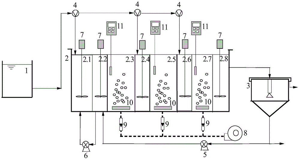
[0021] The present invention will be further explained below in conjunction with the drawings: figure 1 As shown, a device for strengthening internal carbon source denitrification based on UCT segmented water inflow process is characterized by:

[0022] Including water inlet tank 1, main reactor 2, sedimentation tank 3, water inlet pump 4, sludge return pump 5, internal return pump 6, stirrer 7, air pump 8, gas flow meter 9, etc. The inlet tank 1 is connected to the first anaerobic zone 2.1, the second anoxic zone 2.4, and the third anoxic zone 2.6 in the main reactor 2 through the inlet pump 4 and the inlet pipeline; The four-stage anoxic zone 2.8 is connected to the sedimentation tank 3 through a water pipe, and part of the sludge at the bottom of the sedimentation tank 3 flows back to the first-stage anoxic zone 2.2 through the sludge return pipeline and the sludge return pump 5, and the first-stage anoxic zone 2.2 Part of the sludge is returned to the first-stage anaerobic z...


PUM


Abstract

The invention relates to a device and a method for strengthening denitrification and advanced nitrogen removal of an internal carbon source by an improved UCT sectional water feeding process, and belongs to the technical field of biological method wastewater treatment. According to the existing UCT sectional water feeding process, the nitrogen removal effect is poor under the condition of domestic sewage with extremely low carbon-to-nitrogen ratio; by an internal carbon source nitrogen removal technology, an external carbon source can be saved, and the reduction of sludge can be realized; according to the device and the method, the internal carbon source technology and the UCT sectional water feeding process are combined; an anoxic reaction zone is added behind the last section of aerobic zone; an advanced nitrogen removal process with internal carbon source denitrification and synchronous nitrification and denitrification effects is developed. By using the method and the device, the water quality of outlet water can be stabilized; the internal carbon source storage capacity of sludge is improved without the external carbon source; the synchronous nitrification and denitrification effect is strengthened; the total nitrogen removal rate is improved; the sludge discharging amount is reduced.

Description

Technical field: [0001] The invention relates to a UCT segmented water inlet process to strengthen internal carbon source denitrification biological denitrification and phosphorus removal device, belonging to the technical field of biological sewage treatment. Without adding new structures, add a post-anoxic reaction zone after the third aerobic reaction zone of the UCT segmented water inlet reactor, and adjust the process parameters appropriately to strengthen the sludge carbon source storage ability. Improve the ability to use carbon sources in sludge for denitrification, and realize simultaneous nitrification and denitrification and sludge reduction with simultaneous nitrogen and phosphorus removal technology. It is especially suitable for the upgrading and transformation of urban sewage treatment plants. Background technique [0002] The UCT segmented water inflow process combines UCT and A / O segmented water inflow processes, and at the same time has the advantages of denit...

Claims


Application Information

Patent Timeline
Patent Type & Authority Patents(China)
IPC IPC(8): C02F3/30
CPCC02F3/308C02F2301/08
Inventor 王淑莹王慰张琼彭永臻
Owner BEIJING UNIV OF TECH
Features
  • R&D
  • Intellectual Property
  • Life Sciences
  • Materials
  • Tech Scout
  • Unparalleled Data Quality
  • Higher Quality Content
  • 60% Fewer Hallucinations
Learn More