Water cooling roller

A technology of water-cooled rollers and rollers, applied in heat treatment equipment, furnaces, heat treatment furnaces, etc., can solve the problems of large cross-sectional size differences of forgings, high production costs of water-cooled rollers, and increased motor power selection, etc., to achieve good strip shape , good airtight testability, and the effect of improving the yield of equipment

Active Publication Date: 2015-04-29
WISDRI WUHAN WIS IND FURNACE
View PDF3 Cites 7 Cited by
  • Summary
  • Abstract
  • Description
  • Claims
  • Application Information

AI Technical Summary

Problems solved by technology

However, the shaft head of the water-cooled roller is forged in one piece, the cross-sectional size of the forgings varies greatly, and the whole equipment is also heavy. Whether it is rough forging, machining, or assembly, there are certain difficulties, which leads to high production costs of the water-cooled roller.
The weight of the water-cooled roller is too large, which also increases the power selection of the motor, which virtually increases the production and operation costs of the enterprise

Method used


Image

  • Water cooling roller
  • Water cooling roller

Examples


Embodiment Construction

[0016] In order to have a clearer understanding of the technical features, purposes and effects of the present invention, the specific implementation manners of the present invention will now be described in detail with reference to the accompanying drawings.

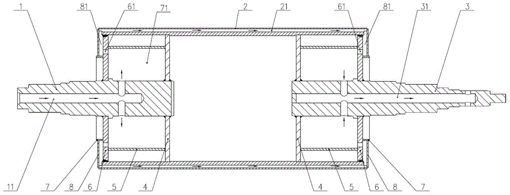
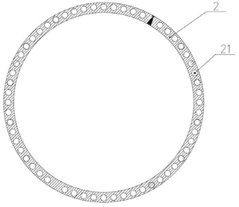
[0017] Such as figure 1 , figure 2 As shown, the water-cooled roller of the present invention includes an operating side shaft cylinder, a roller 2, and a transmission side shaft cylinder. The operation side shaft cylinder is composed of operation side shaft 1, inner end plate 4, outer end plate 6, cylinder 5, inner plate 7 and cover plate 8, and the transmission side shaft cylinder is composed of transmission side shaft 3, inner end plate 4, outer end Plate 6, cylinder 5, inner plate 7 and cover plate 8 are formed.

[0018] A first water channel 11 is provided inside the operation side shaft 1 , and the first water channel 11 communicates with the inner chamber 71 formed by the inner end plate 4 , the outer end plat...


PUM


Abstract

The invention relates to a water cooling roller. The water cooling roller comprises an operating side shaft, a transmission side shaft and a roller, wherein inner plates, outer end plates and inner end plates are arranged on the operating side shaft and the transmission side shaft; a cylinder is arranged between the inner end plate and the outer end plate; a cover plate is arranged between the inner plate and the roller; the inner end plate, the outer end plate and the cylinder form an inner cavity; the inner plate, the cover plate, the outer end plate and the roller form an outer cavity; holes communicated with the inner cavity and the outer cavity are uniformly formed in the outer end plate; a first water channel is formed inside the operating side shaft; a plurality of second water channels penetrating through in the axial direction are uniformly formed in the wall thickness periphery direction of the roller; a third water channel is formed inside a driven side shaft; the first water channel is communicated with the inner cavity on an operating side; the second water channels are communicated with the inner cavity on a transmission side; the third water channel is communicated with the outer cavity on the operating side and the outer cavity on the transmission side. The water cooling roller has the advantages that by performing optimization design on the structure of the water cooling roller, the application of large-section forge pieces is reduced, the equipment manufacture cost is reduced, the water cooling roller is high in cooling speed and uniform in cooling, and the strip steel shape is good.

Description

technical field [0001] The invention relates to equipment of a cold rolling continuous annealing unit, and more specifically relates to a water-cooled roll. Background technique [0002] In the cold-rolled strip steel annealing unit, the roll cooling technology is to make the strip steel contact with the furnace roll with cooling water inside, and realize the cooling of the strip steel through heat conduction. This technology has low production cost and can realize rapid cooling. It is suitable for the production of cold-rolled strips and be widely used. However, the shaft head of the water-cooled roller is integrally forged, and the cross-sectional dimensions of the forgings are quite different. The weight of the water-cooled roller is too large, which also increases the power selection of the motor, which virtually increases the production and operation costs of the enterprise. Contents of the invention [0003] The technical problem to be solved by the present inventi...

Claims


Application Information

Patent Timeline
Patent Type & Authority Applications(China)
IPC IPC(8): C21D1/26C21D9/52
CPCC21D1/26C21D9/0012C21D9/52
Inventor 姚文方田发禹徐祖敦盛解平张荣明
Owner WISDRI WUHAN WIS IND FURNACE
Why Eureka
Try Eureka