Embedded type steel anchor box

A steel anchor box and embedded technology, which is applied in bridge parts, bridges, buildings, etc., can solve the problems of large and complex bridge tower structures, cracking of tower wall concrete, and reduction of horizontal force, etc., achieving good application prospects and strong prefabrication , the effect of reducing the horizontal force

Inactive Publication Date: 2015-04-29
DALIAN UNIV OF TECH
View PDF6 Cites 9 Cited by
  • Summary
  • Abstract
  • Description
  • Claims
  • Application Information

AI Technical Summary

Problems solved by technology

The force transmission mechanism of the steel anchor box anchoring method is that the horizontal component force of the cables on both sides of the tower column is jointly borne by the horizontal steel plates of the anchor box and the tower column, and the vertical component force is transmitted to the anchor box through the shear keys of the vertical steel plates on both sides of the anchor box. On the concrete of the tower column, the main disadvantage of this anchorage form is that the tower wall shares a large horizontal force, which is enough to crack the tower wall concrete
The force transmission mechanism of the steel anchor beam anchorage form is that the vertical component force of the cable is transmitted from the vertical support of the steel anchor beam to the tower column through the corbel. When the horizontal component force of the cable on both sides is equal, the horizontal component force of the cable is completely The steel anchor beam bears it by itself. When the horizontal force components of the stay cables on both sides are not equal, the unbalanced horizontal force of the stay cables is finally transmitted to the tower wall through the support friction resistance under the steel beam or the limit stops along the bridge to both ends. The anchoring method greatly reduces the horizontal force borne by the tower wall, but it requires enough space in the tower to place steel anchor beams, and a corbel structure needs to be added in the tower, which makes the entire bridge tower structure large and complex, so this anchoring form is in the middle Difficult to implement on small cable-stayed bridges

Method used


Image

  • Embedded type steel anchor box
  • Embedded type steel anchor box
  • Embedded type steel anchor box

Examples


Embodiment Construction

[0015] The specific embodiments of the present invention will be described in detail below in conjunction with the technical solutions and accompanying drawings.

[0016] The embedded steel anchor box is divided into main structure part and auxiliary structure part

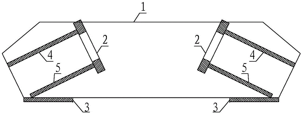
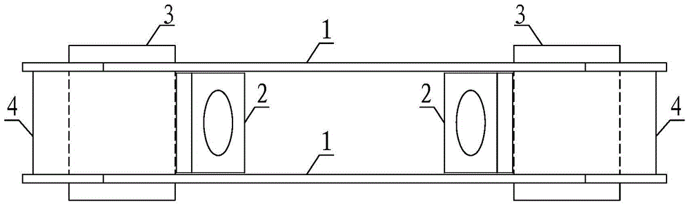
[0017] The main part of the steel anchor box has two horizontal steel pull plates 1. The size of the horizontal steel pull plates is determined according to the horizontal component force of the cables. The two horizontal steel pull plates are arranged in parallel. The pull plates are arranged in parallel, the angle is the same as that of the stay cables, the anchor plate 2 is connected with the upper force plate 4 and the lower force transfer plate 5, and is vertically arranged with the stay cables, and the seat plate 3 is connected with the horizontal steel pull plate , arranged at the bottom of the entire anchor box, and all connections of the main part of the steel anchor box are welded.

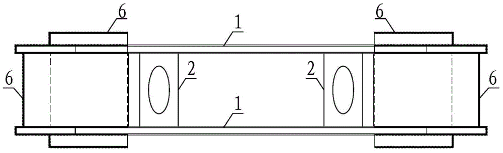
[0018] The attached...


PUM


Abstract

The invention provides an embedded type steel anchor box, and belongs to the technical field of bridge structure design. The embedded type steel anchor box comprises a horizontal steel pulling plate, an anchor bearing plate, a seat plate, an upper force transfer plate, a lower force transfer plate, a rubber plate and a felt. The rubber plate forms a deformation cushion zone between the steel anchor beam and the concrete at the joint surface of the steel and concrete; the horizontal component force of the inhaul cable is maximally suffered by the steel anchor box via the deformation effect of the deformation cushion zone, thereby greatly reducing the horizontal force suffered by the tower wall, thus ensuring the load-bearing safety of the tower columns. The embedded type steel anchor box can be widely applied to the field of engineering design; such an embedded type steel anchor box can be installed in smaller space of tower columns of medium and small scales of cable-stayed bridge; the stress of the concrete tower wall is greatly reduced at the same time. The embedded type steel anchor box makes the structure design more flexible, makes the stress more reasonable, and makes the engineering construction convenient.

Description

technical field [0001] The invention belongs to the technical field of bridge structure design, and relates to the structural design of a main force-bearing component of a cable-stayed bridge, in particular to a steel anchor beam that can be embedded in concrete. Background technique [0002] At present, the tower body is a cable-stayed bridge with a concrete structure, and the anchorage methods of the stay cables on the tower mainly adopt steel anchor box anchorage and steel anchor beam anchorage. The force transmission mechanism of the steel anchor box anchoring method is that the horizontal component force of the cables on both sides of the tower column is jointly borne by the horizontal steel plates of the anchor box and the tower column, and the vertical component force is transmitted to the anchor box through the shear keys of the vertical steel plates on both sides of the anchor box. On the concrete of the tower column, the main disadvantage of this anchorage form is ...

Claims


Application Information

Patent Timeline
Patent Type & Authority Applications(China)
IPC IPC(8): E01D19/14
CPCE01D19/14
Inventor 邱文亮姜涛张哲黄才良王骞石磊王峥峥
Owner DALIAN UNIV OF TECH
Why Eureka
Try Eureka