Testing mechanism for concrete creep under corrosion action, application and creep testing method

A technology of corrosion action and testing mechanism, applied in the direction of weather resistance/light resistance/corrosion resistance, measuring devices, instruments, etc., can solve problems such as erosion, and achieve the effect of simple loading, convenient operation, and important engineering application value

Active Publication Date: 2016-08-24
HUNAN CITY UNIV
View PDF4 Cites 11 Cited by
  • Summary
  • Abstract
  • Description
  • Claims
  • Application Information

AI Technical Summary

Problems solved by technology

In actual engineering, the structure is eroded by the external environment while bearing the load, and only considering the creep of concrete under the stress alone cannot fully reflect the actual coupling effect of the structure

Method used


Image

  • Testing mechanism for concrete creep under corrosion action, application and creep testing method
  • Testing mechanism for concrete creep under corrosion action, application and creep testing method

Examples


Embodiment 1

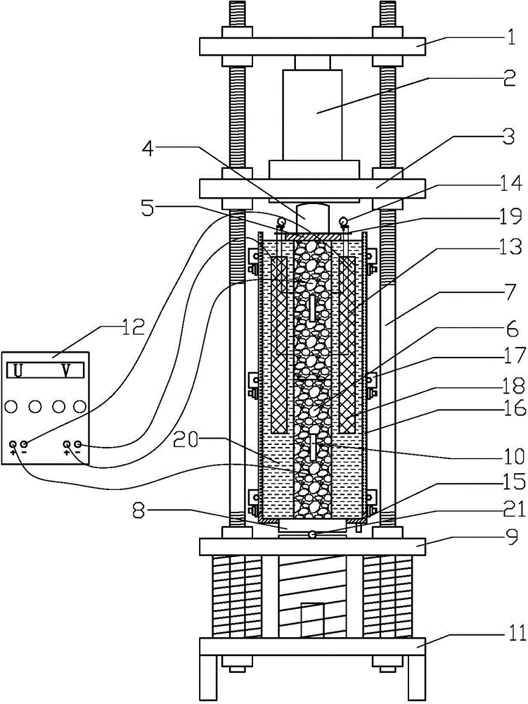
[0024] Depend on figure 1 As can be seen, a concrete creep test mechanism under corrosion, it comprises the stressed steel plate 5 and the pressure sensor 4 that are installed on the top of the test specimen 6, and the test specimen 6 is installed in the center of the open container filled with the corrosive solution 20; Corrosion solution 20 is provided with conductive metal mesh 18, the steel bar in the test specimen 6 is connected with the positive pole of constant voltage direct current power supply 12, and conductive metal mesh 18 is connected with the negative pole of constant voltage direct current power supply 12, by corrosion solution 20, constant voltage direct current The power supply 12 , the conductive metal mesh 18 and the test piece 6 form an electrochemical corrosion circuit; the dial indicator 14 is installed on the test piece 6 .

[0025] For the convenience of observation, the open container of the present invention includes a bottom tank 15 on which high-st...

Embodiment 2

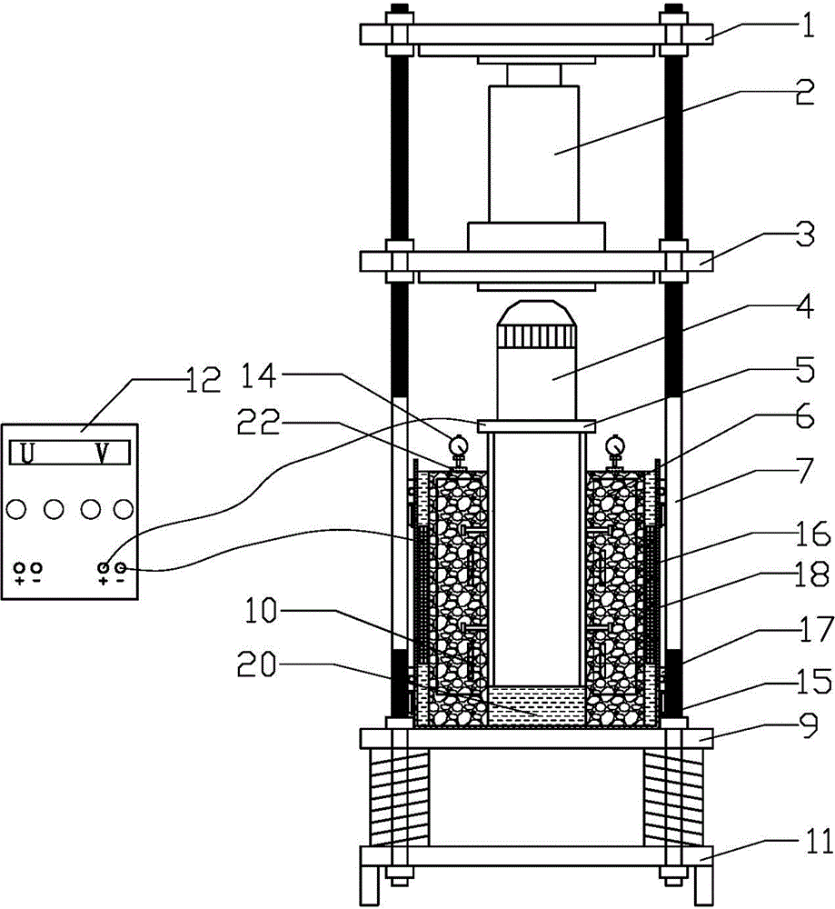
[0044] Depend on figure 2 It can be seen that the test specimen 6 of the present embodiment 2 is a steel-concrete composite structure, and the steel frame and the concrete are connected by bolts; The surface is uneven, and a glass block 22 is arranged between the measuring head and the concrete part on the top of the test specimen 6 . Because the dial gauge 14 is not installed in the corrosion solution 20, therefore, the dial gauge 14 is not needed to be installed outside the corrosion solution 20 without the installation rod, and the corrosion solution 20 is a sodium sulfate solution of 5% mass fraction.

[0045] The rest are the same as embodiment 1.


PUM


Abstract

The invention discloses a testing mechanism for concrete creep under the corrosion and load coupling action. The testing mechanism comprises a stress steel plate and a pressure sensor, wherein the stress steel plate is installed on the upper portion of a testing sample. The testing mechanism is characterized in that the testing sample is installed in the center of an open container containing a corrosion solution; a conductive metal net is arranged in the corrosion solution, a steel bar in the testing sample is connected with the positive electrode of a constant-voltage direct-current power source, the conductive metal net is connected with the negative electrode of the constant-voltage direct-current power source, and an electrochemical corrosion circuit is formed by the corrosion solution, the constant-voltage direct-current power source, the conductive metal net and the testing sample; a dial indicator is installed on the testing sample. The creep testing method of the testing mechanism comprises the first step of manufacturing of the testing sample, the second step of installation, the third step of loading and the like. The creep characteristics of concrete under the corrosion and load coupling action are taken into consideration and better conform to the environment state of practical engineering structures, tests have higher engineering value, and significant engineering application value and wide market application prospects are achieved.

Description

technical field [0001] The invention relates to a concrete creep test, in particular to a concrete creep test mechanism under corrosion and its application and creep test method, in particular to a concrete creep test mechanism and its application under the coupled action of corrosion and load. Applications and creep test methods. Background technique [0002] The reliability of engineering structures includes safety, applicability and durability. Durability can be divided into material durability and structural durability. Material durability is determined by the material properties of concrete and steel bars, including shrinkage and creep of concrete and corrosion of steel bars. Structural durability is determined by the erosion of the structure. determined by the environment. Usually engineering structures are in a complex erosion environment, so the durability of the structure is also the result of the joint action of the environment and material properties. [0003] ...

Claims


Application Information

Patent Timeline
Patent Type & Authority Applications(China)
IPC IPC(8): G01N3/00G01N17/00
CPCG01N3/00G01N17/00
Inventor 曹国辉阳亮彭细荣蔡文武贺冉
Owner HUNAN CITY UNIV
Why Eureka
Try Eureka