Rigidity-heterosexual type combined shear connector

A technology for connecting parts and elastic parts, which is applied in the field of steel and concrete composite structures, can solve the problems of weak shear strength of the joint surface, large stress on welding studs, and excessively dense welding studs, and achieves good economic benefits and scientific research value. High accuracy and versatility

Inactive Publication Date: 2013-03-13
TONGJI UNIV
View PDF3 Cites 9 Cited by
  • Summary
  • Abstract
  • Description
  • Claims
  • Application Information

AI Technical Summary

Problems solved by technology

Under the effects of constant live load, concrete shrinkage and temperature, when using welding studs of several specifications specified in the code for layout design, the shear stiffness of the joint surface, the shear bearing capacity, and the stress of the concrete often occur. And the mutual constraints and inconsistencies of the force of the welding studs: using small-sized welding studs, the

Method used


Image

  • Rigidity-heterosexual type combined shear connector
  • Rigidity-heterosexual type combined shear connector
  • Rigidity-heterosexual type combined shear connector

Examples


Embodiment 1

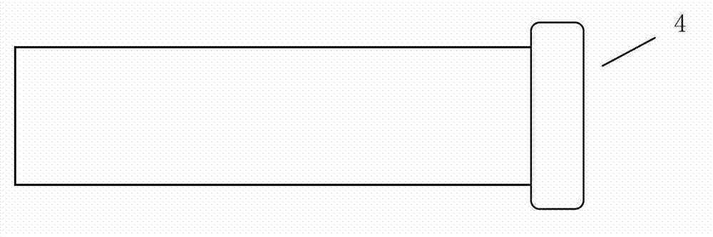
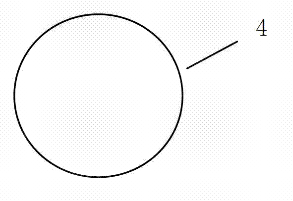
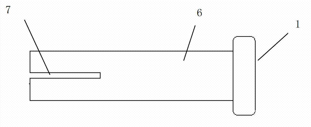
[0036] Please also see Figure 2a , 2b . A slit 7 is cut out along the direction of the nail rod 6 at the root of the welding stud 4 by using a slitting machine, and then the slit welding stud 1 is obtained. The gap 7 is located at the diameter position of the nail rod 6 . The diameter and height of the welding stud 4 are determined by the design requirements of the shear bearing capacity of the steel-concrete joint surface. The width of the gap 7 should be between 0.5mm-1.0mm, and the height is determined by the design requirements of the shear stiffness of the steel-concrete joint surface, but should not exceed 3 / 4 of the height of the selected nail rod 6 . In order to avoid excessive reduction of the shear bearing capacity of the connector, the width of the gap 7 should not be too wide, and when the width of the gap 7 is greater than 0.2mm, it can greatly reduce the shear stiffness.

[0037] Compared with the same shear performance in all directions of welding stud 4, t...

Embodiment 2

[0044] Such as Figure 4a , 4b As shown, a slit 13 is cut on the kerf welding stud 12, and the slit 13 deviates from the position of the diameter. In this way, the reduction degree of the shear stiffness of the seam welding stud 12 is slightly smaller than that of the seam welding stud 1 in the first embodiment.

Embodiment 3

[0046] Figure 5a , 5bAs a modification of Embodiment 2, on the kerf welding stud 10, the slit 11 deviates from the diameter and has a smaller arc relative to the nail shank, that is, the arc height H of the slit 11 and the horizontal projection length L of the arc The ratio is less than or equal to 1 / 10. By changing the width and length of the gaps 11 and 13, seam welding studs with different shear rigidities can be obtained. The shape of the gap curve is designed to be consistent with the shear deformation of the welding stud, so that the welding stud is more prone to shear deformation and the shear stiffness is smaller.


PUM

PropertyMeasurementUnit
Gap widthaaaaaaaaaa

Abstract

The invention discloses a combined shear connector, which comprises welding studs, wherein at least one gap is formed at the root of each welding stud in a stud rod direction; and an elastic piece is filled in each gap. The invention further provides a combined structure formed by the combined shear connector, a steel member and a concrete member, wherein the combined shear connector is in welded connection with the steel member; the concrete member is poured on the steel member; and the gap width direction of the gap is consistent with a smaller shear rigidity direction of a combined surface of the steel member and the concrete member, and orthogonal with a larger shear rigidity direction of the combined surface of the steel member and the concrete member. The combined structure has the advantages that while reliable shear rigidity of the combined surface of the steel member and the concrete member is guaranteed, shear rigidity of the combined surface is reduced; concrete tensile stress caused by concrete shrinkage and temperature changes in the combined structure of the steel member and the concrete member is effectively reduced; and initial shear rigidity of a combined surface of a prestressed concrete bridge deck slab and a steel beam is reduced and a prestress application effect is effectively increased.

Description

technical field [0001] The invention belongs to the field of combined structures of steel and concrete, in particular to a shear connector for the combined surface of steel and concrete. Background technique [0002] Composite structure is the third structural form next to steel structure and concrete structure. Among them, the steel and concrete composite structure rationally uses steel with strong tensile properties and concrete with strong compressive properties in the tension zone and compression zone of the component, which has excellent mechanical properties and high economic efficiency. It is widely used in bridge engineering and structural engineering. [0003] In the steel-concrete composite structure, the shear connectors on the steel-concrete interface play a role in combining the two materials and have a great influence on the mechanical performance of the composite structure. Welded stud connectors are the most commonly used form of connectors in composite str...

Claims


Application Information

Patent Timeline
IPC IPC(8): E04B1/41
Inventor 刘玉擎徐骁青蔺钊飞
Owner TONGJI UNIV
Why Eureka
Try Eureka